
Water in a closed hydraulic system
Water is mostly used as a heat transfer medium in heat generation and heat distribution systems. With 4.19 kJ/kgK, it has a high specific heat capacity and is characterised by high availability and environmental compatibility. However, the quality of water found in nature varies from region to region. Metals and salts are often dissolved in water, as are gases such as O2 and CO2.
These may cause problems and damage in the heating system, which is why the water must undergo water treatment. The required water quality depends on the heat generator output, the maximum operating temperature and the materials used in the system.
Required water quality
The values for heating water quality in large-scale systems are set out in VDI 2035 and the AGFW worksheet FW 510 (or TECH 1466 from VdTÜV). The table “Water quality overview” provides an overview of the respective values.
| VDI 2035 | AGFW FW 510/TECH 1466 (VdTÜV) | ||||
| Range of applications | Heating water systems | Heating and hot water systems | |||
| Temperature range | Up to 100 °C | From 100 °C | |||
| Conductivity at 25 °C | Low-salt: | Containing salt: | Low-salt: | Containing salt: | |
| 10 to 100 | 100 to 1,500 | 10 to 30 | 30 to 100 | 100 to 1,500 | |
| Appearance | Clear, free of sedimenting substances | Clear, free from suspended substances | |||
| pH value at 25 °C | Without aluminium alloys | With aluminium alloys | 9.0 to 10.0 | 9.0 to 10.5 | 9.0 to 10.5 |
| 8.2 to 10.0 | 8.2 to 9.0 | ||||
| Hardness (alkaline earth) [mmol/l] | < 0.05 | < 0.02 | |||
| Oxygen [mg/l] | As low as possible | < 0.1 | < 0.05 | < 0.02 | |
Overview of water quality (own representation based on VDI 2035, 2021, p.24 and TECH 1466, 2014, p.11)
Information about operator training courses and water seminars
Constant monitoring of the water characteristics is an important factor for the economical and trouble-free operation of the heating system. Continuous monitoring of the relevant parameters enables a rapid response to changes in the circulating water and protects the heat generator and heat consumers from damage.
To analyse the circulating water, a sample is taken at a sampling point in the system, as close as possible to the boiler in the return. We recommend that samples be taken and analysed at regular intervals. We recommend using a water sample cooler to cool the water sample to the analysis temperature of 25 °C.
In addition to the water quality, the volumes of water used for filling and topping up should also be recorded, in order, amongst other things, to identify water losses in good time.
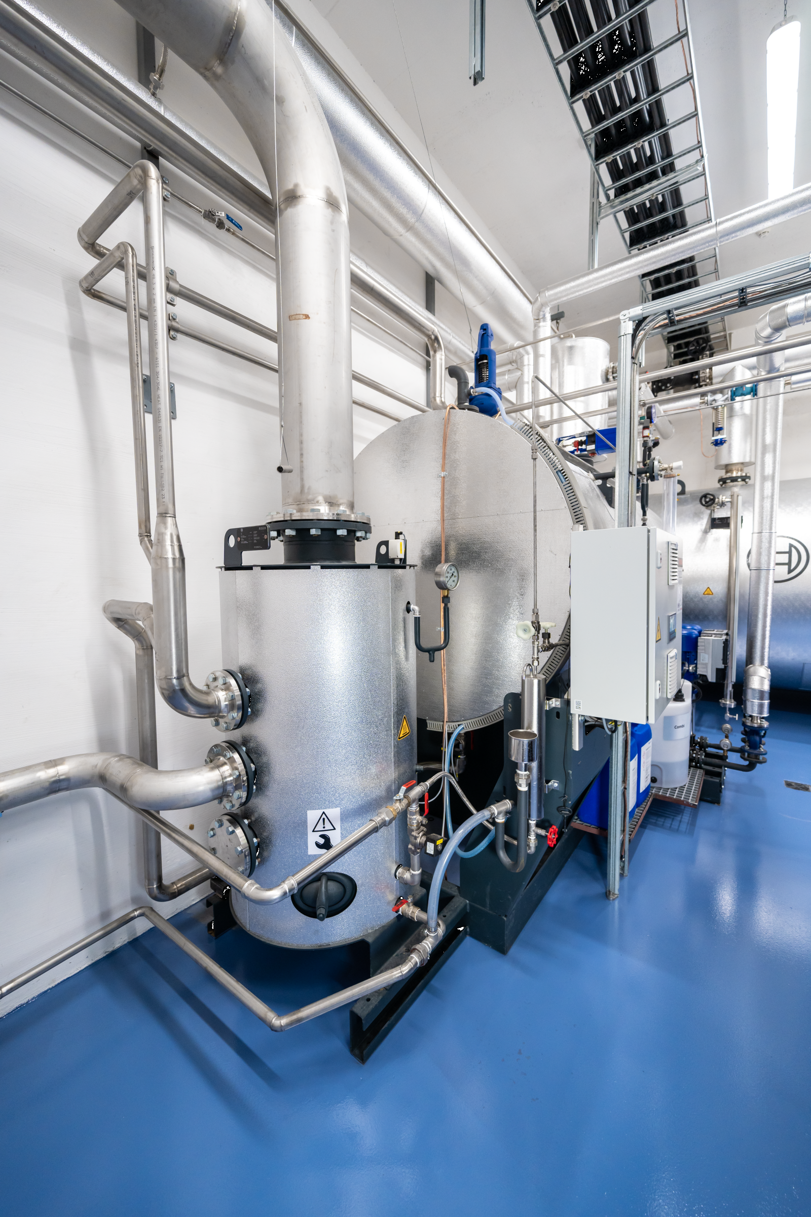
Water sample cooler for safe water sampling to test water quality
Water treatment
Correct water treatment, particularly for filling and refilling, is one of the most important prerequisites for safe and long-lasting operation.
The commonly used terms and their synonyms for the various water flows are briefly explained below.
| Fresh water (raw water) |
Untreated water sourced from the following sources:
|
| Softened water (soft water) |
Water from which calcium (Ca2⁺) and magnesium (Mg2⁺) ions have been removed using an ion exchanger. |
| Partially desalinated water (permeate or demineralised water) |
Water that contains virtually no salts. It has a conductivity of < 50 µS/cm and is usually produced from softened water by reverse osmosis. |
| Purified water (purified water, demineralised water) |
Water that no longer contains any salts. It has a conductivity of < 1 µS/cm and is usually produced from the combination of anion and cation exchangers. |
| Fill water | Treated water used for the initial, new or partial filling of district heating systems. |
| Top-up water | Treated water used to compensate for temperature-related changes in volume, as well as losses due to evaporation and leaks. |
| Circulating water | Water that flows through the heat generator, the pipe network and the heat exchangers or heat transfer stations in district heating systems. The term applies not only to primary networks, but also to water in a secondary network. |
These requirements for make-up and feed water help to reduce or prevent the following causes of damage and faults:
- Corrosion
- Deposit build-up on the water side
- Sludge formation
To ensure that water quality standards are met and to prevent damage caused by elevated concentrations of problematic substances in the water, the fresh water must be treated.
To this end, various water-treatment measures are employed, depending on the capacity of the boiler systems, the size of the heating network and the constituents of the available fresh water.
The following diagram provides an overview of the substances present in fresh water, the resulting risks to the heating system, and the measures that need to be taken during water treatment.
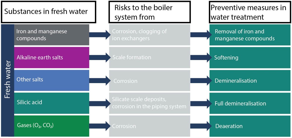
Substances found in fresh water for hot water boilers
The design of a water treatment plant should always be based on a detailed analysis of the quality of the available fresh water.
Iron removal and manganese removal
During iron and manganese removal, iron(II) ions (Fe2+) and manganese(II) ions (Mn2+) dissolved in the water are first oxidised to higher-valent ions. Oxidation can take place using oxygen (O2), other oxidising chemicals such as potassium permanganate (KMnO4), or via catalysis. The resulting precipitates can then be filtered out using filter granules.
Softening
Of all the substances dissolved in water, it is water hardness in particular that is especially harmful to the operation of a boiler system. The term “hardness” mainly refers to calcium and magnesium ions (Ca2+; Mg2+). If these so-called alkaline-earth metals are present, they can precipitate when the boiler is heated, forming scale (CACO3), which builds up as a deposit on the heating surfaces.
If the build-up of layers or deposits is not detected at an early stage, efficiency will be reduced due to the obstruction of heat transfer. If the layer thicknesses continue to increase, this may lead to the heating surfaces overheating and cause serious damage, potentially resulting in the boiler being written off. To prevent this, the substances causing hardness must be removed from the water.
How ion exchangers work
Ion exchange is the most commonly used method of water softening. In this process, the substances responsible for water hardness – calcium and magnesium – are replaced by sodium. The ion exchange is a simple and efficient method of water softening, involving only minimal costs for the consumption of special regenerating salt.
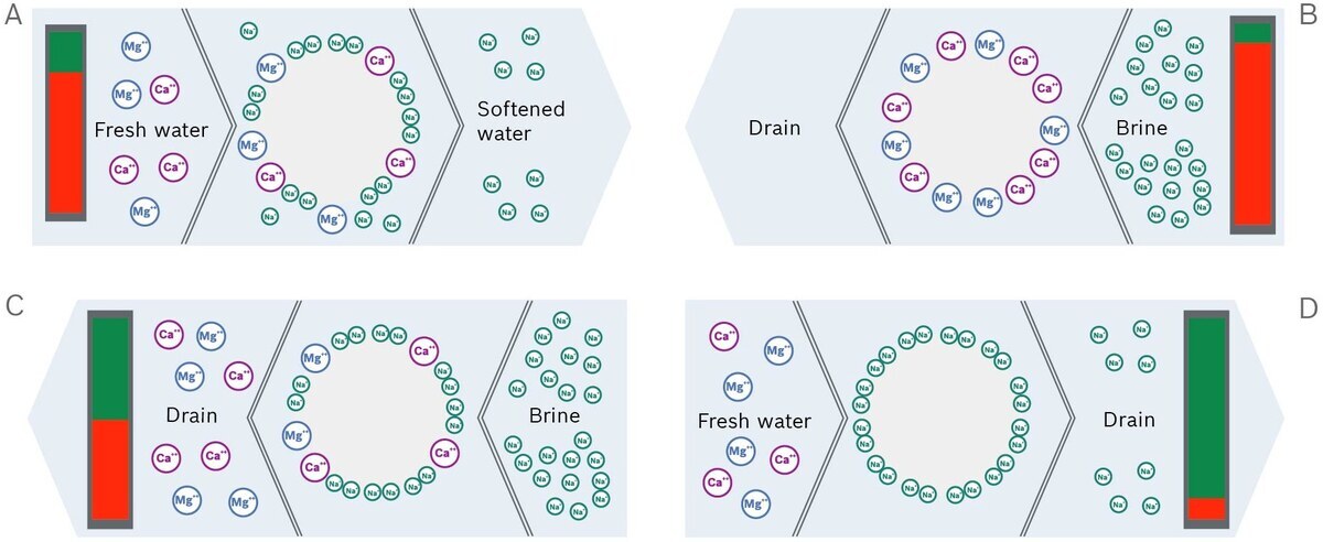
How an ion exchanger works for water softening
Operating state A: Water softening
When water is softened by ion exchange, a chemical equilibrium reaction takes place. Sodium ions adhere to the exchange resin contained in the water softener. As soon as water containing lime flows through the softening system, the calcium and magnesium ions contained in the fresh water are bound to the exchange resin. This releases sodium ions in exchange.
Operating state B: Start of regeneration
The exchanger resin absorbs new hardness components until it is saturated. Then the ion exchanger resin has to be regenerated. To do this, special softening salt (NaCl) is required, which is dissolved in water to form brine.
During regeneration, the exchanger resin is purged with the brine. Due to the excess of sodium in the brine, the resin releases the calcium and magnesium ions again and absorbs the sodium ions.
Operating state C: End of regeneration
As the resin primarily binds calcium and magnesium ions, it cannot be fully regenerated. It is therefore recommended that you only use water softeners with a so-called economic brining.
Operating state D: Resumption of water softening
When the regeneration process is completed, the ion exchanger is ready for another cycle of water softening.
With the continuous replenishment of supplementary water, dual systems must be used. In a dual system, the second ion exchanger is regenerated whilst the first is in operation.
This guarantees a constant supply of softened water.
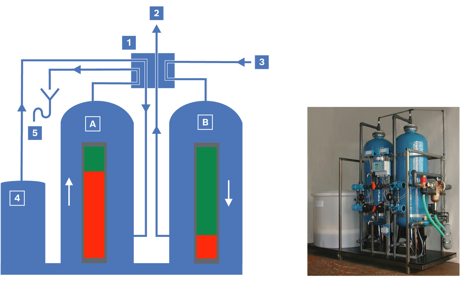
Schematic and illustrative representation of a dual water-softening system
|
|
Operating state A: The ion exchanger is regenerated in the counter-current |
|
|
Operating state B: Ion exchanger in operation |


|
|
Switch-over fitting: illustration showing the current flow |
|
|
Softened make-up water |
|
|
Fresh water |
|
|
Container for regenerating solution |
|
|
Waste water |


|
Separation process |
Screen filtration |
Fine filtration |
Particle filtration |
Micro-filtration |
Ultra-filtration |
Nano-filtration |
Reverse osmosis |
|
Separation limits |
> 500 µm |
5 ... 500 µm |
1 ... 10 µm |
0.1 ... 1 µm |
0.01 ... 0.1 µm |
0.001 ... 0.01 µm |
< 0.001 µm |
|
Removable substances |
Grains, |
Larger |
Small |
Microparticles, germs, bacteria, viruses |
Viruses and molecular substances |
Low-molecular-weight substances and humic substances |
Ions |
|
Processes in water technology |
Screening, cyclones, sedimentation, clarification |
Fabric filters, cloth filters |
Multi-layer rapid filter, membrane filtration (MF) |
Multi-layer slow filter, membrane filtration (MF) |
Membrane filtration (UF) |
Membrane filtration (NF) |
Reverse osmosis (RO) |
|
Separation limits |

|
||||||
General overview of separation limits and separation processes in water treatment
The purified water produced is available on a continuous basis, and the resulting concentrate can be discharged into the sewer system without further treatment.
For systems with lower capacity, water softening is a prerequisite for the use of a reverse osmosis system. For higher flow rates, the water softener can be installed downstream as a safety filter; however, in this case, the water must first be chemically treated to prevent the diaphragms from becoming blocked.
Another prerequisite for the use of reverse osmosis is clear water, free from insoluble foreign substances and, in particular, free from organic contaminants, in order to prevent blockages.
The softened water is fed under high pressure into the modules fitted with a diaphragm. Pure water and a minimal amount of small salt ions diffuse through the membrane to form the permeate (Latin: permeare = to pass through), which is available as partially desalinated water. The permeate fraction of the water used is 80 – 95 %. The remainder (5 – 20 %) of the original volume of water is the high-salinity concentrate, also known as retentate (Latin: retinere = to retain), which is usually discarded unless it can be put to another use.
The reverse osmosis process operates continuously, retaining around 98 % of the salts, resulting in a conductivity of less than approximately 20 μS/cm in the permeate (depending on the conductivity of the feed water). The system’s correct operation is monitored by measuring the conductivity of the permeate. To keep the reverse osmosis systems as compact as possible, it is advisable to use a permeate collection tank. This is then used to replenish the supply.
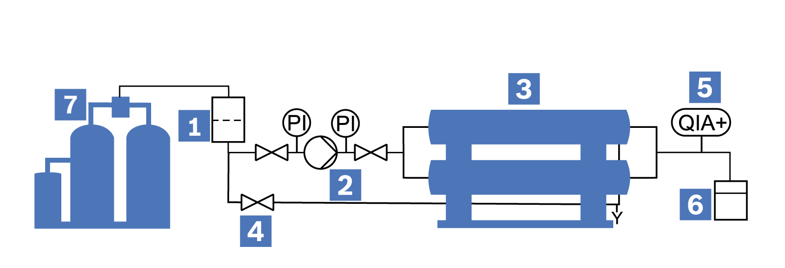
Schematic diagram of a reverse osmosis system
|
|
Filter |
|
|
High-pressure pump |
|
|
Reverse osmosis modules |
|
|
Bypass |
|
|
Conductivity monitoring (QIA+) |
|
|
Permeate container |
|
|
WTM water treatment module |


Oxygen removal
In district heating networks, it is not always possible to prevent oxygen ingress. In a largely closed district heating network with no increased need for supplementary water, the level of oxygen ingress during trouble-free operation is so low that there is no risk of corrosion damage. It is not necessary to remove the oxygen in this case. However, an oxygen-binding agent may be added.
Oxygen removal, on the other hand, is advisable if, due to specific operating conditions, an increased influx of oxygen cannot be ruled out.
This can be achieved by using partial-flow deaeration systems, through catalytic and electrochemical oxygen removal, and by adding an oxygen-binding agent scavenger.
Chemical dosing
To reliably ensure and monitor the required water quality, the properties of the heating water can be improved through additional chemical treatment. Chemical dosing helps to ensure the following:
- Binding of residual oxygen
- Reduction of corrosion by adjusting the pH value
- Stabilisation of the residual hardness
- Prevention of deposits and limescale build-up
Sodium sulphite is typically used to bind oxygen, whilst trisodium phosphate is used to bind residual hardness and raise the pH value.
Water disposal – flue gas condensate
Flue gas condensate is produced intermittently when the boiler system is started from a cold state, and continuously when using condensing technology via a condensing flue gas heat exchanger. This condensate is acidic (pH value < 4) and must be neutralised before being discharged into the sewer system in order to comply with the discharge requirements for waste water into the public sewer network.
Depending on the volume of condensate produced, either granular or liquid neutralisation systems are used for this purpose.
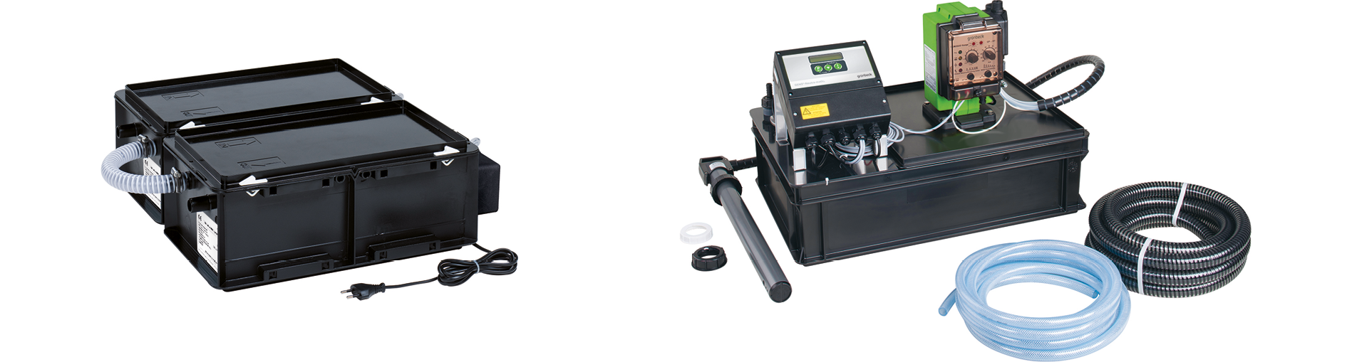
Neutralising systems for flue gas condensate (granular neutralisation on the left, liquid neutralisation on the right)
Frost protection
In some cases, antifreeze is mixed with the circulating water to prevent the circulating water from freezing in winter. Antifreeze is usually based on monoethylene glycol or propylene glycol (e.g. Antifrogen N). The proportion of antifreeze determines the level of frost protection.

20 % glycol by volume: Frost protection down to -10 °C
40 % glycol by volume: Frost protection down to -25 °C
55 % glycol by volume: Frost protection down to -40 °C
Important:
Due to the changed thermal design of the boiler, the maximum possible output of the boiler changes.
The addition of antifreeze affects the physical properties of the circulating water.
- The water-antifreeze mixture has poorer heat transfer properties than water alone. The temperature difference between the medium temperature and the surface temperature of the flame tube therefore increases, which means that the flame tube is subjected to greater stress in conventionally fired boilers.
- The water-antifreeze mixture has a lower specific heat capacity than water. The mass flow rate of the water-glycol mixture that must be pumped through the boiler, given the temperature spread between the flow and return, is therefore greater than it would be for water alone.
It also has implications for the design of the entire system, e.g. water treatment, valves/fittings or piping.
- Greater pressure loss in the boiler or in the piping.
- Impact on pump design (larger pumps may be required)
- Overall, this results in higher water volumes, higher flue gas temperatures and slightly lower efficiency (a difference of less than 1 %).
- The minimum water level in the boiler remains unaffected, as the only requirement is that there is a flow of water.
- When used in conjunction with antifreeze, it is usually not possible to meet the specified electrical conductivity requirements.
- Only fully demineralised water with a conductivity of < 10 μS/cm is permitted for use as supplementary water.
- Glycol-water mixtures cannot be used without the addition of corrosion inhibitors (which must, however, already be present in the antifreeze) because their corrosive properties are more pronounced than those of water.
- The use of additional dosing agents is not permitted.
- The maximum operating temperature of antifreeze is limited, as antifreeze tends to break down chemically (the maximum operating temperature is generally 110 °C for glycols and 150 °C for Antifrogen).
- Galvanised pipes are not permitted in the hot water network, as antifreeze can dissolve zinc.
- Antifreeze has a higher coefficient of thermal expansion.
- The expansion system must therefore be dimensioned larger accordingly.
- Water-antifreeze mixtures may lead to increased sludge formation in combination with foreign substances and/or dissolved salts.