
Increased efficiency at the burner system
Combustion air fan
An optimum fuel/air mixture is necessary for complete combustion. However, industrial boiler systems are often also operated at partial load. Both the fuel and air supply are reduced here.
The combustion air fan without speed regulation also runs at nominal speed in partial load ranges, as in this case the amount of air supplied to the combustion process is throttled purely by closing the air dampers. The fan consumes a high amount of electrical power, which is wasted due to throttling. If the air volume is mainly changed by modulating the speed of the fan, the power input in partial load ranges is much lower.
The reduction in power input is accompanied by a corresponding reduction in noise levels. All systems that are frequently operated at partial load for long periods of time should be equipped with variable-speed fans.
With a burner load profile with average utilisation, this can save around 65 % of electrical energy. This usually results in annual savings in the four-digit euro range, meaning that a variable-speed burner usually pays for itself within a year.
|
Example: |
|
|
Boiler output |
2,500 kW |
|
Burner fan |
10 kW |
|
Electricity saving |
Approx. 51,257 kWh/a (65.5 %) |
|
Cost efficiency |
Approx. €10,251/a (based on an electricity price of €0.20/kWh) as of 2022 |
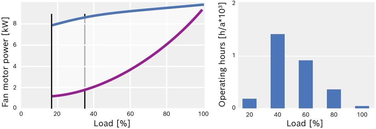
Energy savings thanks to a variable-speed burner fan
Excess air
The ideal in combustion technology is stoichiometric combustion. This is the case when all fuel molecules react completely with the oxygen in the air, leaving no unburned fuel or oxygen behind.
If too little atmospheric oxygen is supplied during the combustion process, only an incomplete combustion reaction can take place. The negative consequence would be the formation of carbon monoxide, a highly toxic gas. If the amount of air is increased too much, all fuel molecules will have already reacted with the oxygen molecules. The remaining oxygen molecules form an unnecessary surplus. Since cold ambient air is usually used as combustion air, an unnecessarily high level of excess air merely heats up this cold combustion air, which is then released into the atmosphere together with the flue gases.
Optimal combustion air adjustment is therefore important for efficiency and safe, low-emission operation. Due to fluctuations in air pressure, air temperature and humidity on the one hand, and fluctuations in fuel quality on the other, which will continue to increase in Germany in the coming years as a result of the further liberalisation of the gas market, a certain level of excess air must be set as a safety measure in comparison to the theoretical optimum. The formation of toxic and explosive carbon monoxide must be prevented under all circumstances. These settings are normally made and checked when the boiler system is commissioned and during the six-monthly or annual maintenance work.
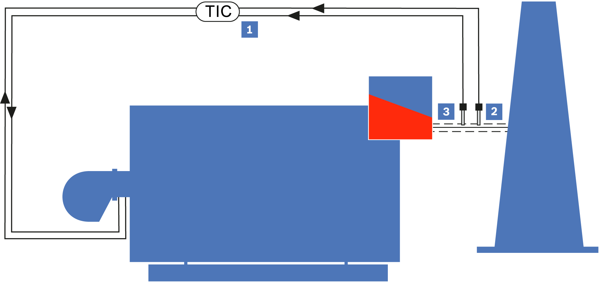
O2 and CO regulation on the hot water boiler (simplified representation)
|
|
Control |
|
|
O2 test probe |
|
|
CO test probe |
|
|
Flue gas |


Continuous measurement and control equipment is necessary in order to operate the systems closer to their optimum operating point, even under changing conditions. An O2 regulation system essentially consists of an oxygen sensor installed in the flue gas flow and a control device. This continuously measures the residual oxygen content in the flue gas and transmits the signal to the burner control system, which readjusts the required air volume.
Combination electrodes (O2 and CO) have been available for several years. In combination with a CO test, the excess air λ can be set even more precisely to the CO limit. By using O2 and CO regulation of the excess air, the excess air of 3 – 4 vol.% oxygen in the flue gas, which is normally set at full load, can be reduced to 0.5 – 1.0 vol.% oxygen. At the same flue gas temperature, this corresponds to a reduction in flue loss of approximately 1 percentage point. CO regulation cannot be applied to oil fuel.
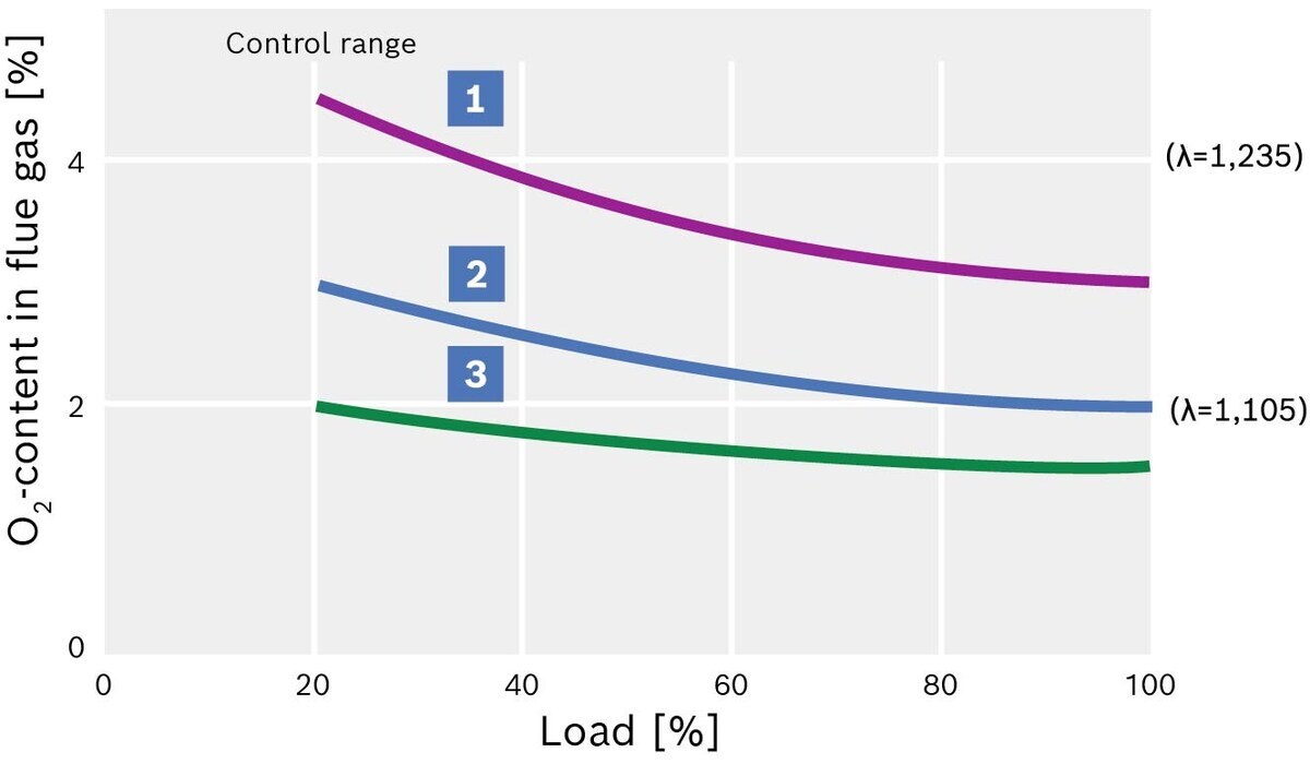
Residual oxygen content and excess air in O2 and CO regulation above the burner load
|
|
Without regulation |
|
|
With O2 regulation |
|
|
With O2 and CO regulation |
Power adjustment
In existing systems, but also in new systems, hot water and heating boilers have far too much boiler output in most operating conditions in relation to the power actually required at any given time.
The reasons for this are:
- Heating load curve over the course of the year. The maximum power is only required on very few days of the year
- Reduction in demand in existing systems, e.g. through the elimination of heating systems or, above all, in local and district heating systems through better insulation of heat consumers
- Subsequent utilisation of existing heat recovery potential
- Oversizing in the planning of new systems
- Excessive safety margins in the design of the actual heat energy demand, e.g. due to incorrect assessment of the simultaneity factors of the consumers, consideration of overly generous power reserves or an as yet unrealised expansion of consumers that has already been taken into account
The result is low or even very low heat consumption in relation to the boiler output. If the heat consumption falls below the minimum load of the combustion, this leads to a high number of burner start-ups and shutdowns. This causes pre-ventilation losses and temperature-induced stresses, which can be extreme, especially during long pre-ventilation periods.
The following measures can be taken to compensate for excessive boiler output:
- Using burners with a wide control range
- Fitting low-load controls, which delay immediate turning up once the burner has been started
- Optimisation of the performance regulation, i.e. the control parameters for the burner switch-on and switch-off points
- Adjustment of the burner output to the actual requirements. This then requires a corresponding burner modification or the installation of a burner with a smaller power range
- Installation of heat cylinders
- Selection of stepped outputs for multi-boiler systems
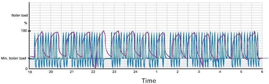
Temperature curve before and after adjusting the burner output in a high-pressure hot water system

Before correction (blue): Unprofitable boiler
Features: Two stage burner control; Burner switch-on interval approx. 7.5 minutes with 35 seconds pre-ventilation time each time; temperature-related alternating loads on the boiler are unnecessarily high here.
Pre-ventilation losses occur every time the burner is ignited.
After correction (purple): Cost-saving boiler
Features: Two-stage burner control, low-load operation during night-time hours; burner switch-on interval approx. 44 minutes with 35 seconds pre-ventilation time each time; temperature-related alternating loads on the boiler are reduced here to a level that does not cause fatigue. Heat loss during pre-purging significantly reduced to one-fifth.
Pre-purging
Before starting the burner, ensure that there are no flammable mixtures in the flue gas paths. In practice, this is achieved by pre-purging. Before the burner ignites the flame, the combustion air fan starts up and forces cold ambient air through the hot flue gas ducts, which are still at operating temperature. The cold air heats up in the process and extracts heat from the boiler. Adequate air change-over is required, which may represent a significant energy loss, especially with frequent burner starts.
In addition to the poor economic efficiency of frequent burner starts, these also reduce the service life. Ideally, 1–2 burner switch-on cycles per hour should be aimed for. If there are more than four burner switch-on cycles per hour, measures should be taken to reduce burner switching, such as adjusting the power.
