
Installation location
Some basic requirements for the boiler installation room are listed below. The information is provided solely as an aid to planning. In addition, all relevant national and local regulations and applicable standards must be observed.
Basic requirements for the installation room
- The installation room must be kept clean and free of dust and dripping water.
- The room temperature must be between 5 °C and 40 °C.
- Unauthorised persons are prohibited from entering the boiler room.
- Sound insulation requirements must be ensured in accordance with local regulations.
- The control panels must be installed in such a way that no vibrations or shocks from the system components can be transmitted to the control panels.
- The installation must be carried out in areas that protect the control panels from excessive heat radiation and ensure accessibility in hazardous situations.
- Where possible, escape routes with emergency off switches must be located opposite each other.
- Sufficient lighting must be ensured, particularly in the area of fittings, control panels and safety equipment.
- In addition, a sufficient number of electrical connection options (sockets) must be provided to supply auxiliary consumers for service and maintenance work.
- There should be mounting options for pipes on walls and ceilings.
- Every boiler installation room should have an exposed external wall or ceiling area of at least 1/10 of the floor area (or in accordance with local requirements), which yields much more easily than the other surrounding walls in the event of overpressure in the boiler installation room. When determining the pressure relief area, national and local regulations as well as the relevant standards must be observed.
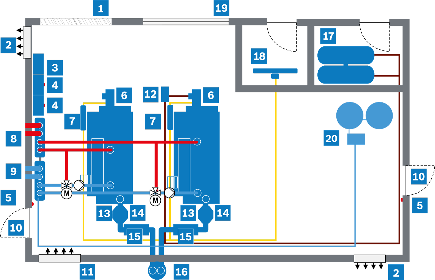
Example illustration of a boiler house (simplified representation)
|
|
Installation |
|
Supply air (bottom) |
|
|
|
Extract air (top) |
|
Oil supply module OSM |
|
|
|
SCO system control |
|
Integrated flue gas heat exchanger ECO |
|
|
|
BCO boiler control |
|
Condensing heat exchanger |
|
|
|
Emergency off switch |
|
Silencer |
|
|
|
Boiler |
|
Chimney |
|
|
|
Gas regulation module GRM |
|
Oil tanks |
|
|
|
Flow manifold |
|
Gas transfer station |
|
|
|
Return manifold |
|
Pressure relief area |
|
|
|
Escape route |
|
Pressure-maintaining system |


|
|
Flow |
|
|
Return |
|
|
Gas |
|
|
Oil |


Accessibility
Boilers and system components should be arranged in such a way that the attached fittings, sensors and all inspection openings remain accessible. Placing the boiler directly against a wall is only advisable to a limited extent for the boiler and some system components. Particular attention should be paid to ensuring that there is a clear passageway at least 1 metre wide on the operating side of the boiler and its components. In addition, care must be taken to ensure that the accessible areas are of sufficient height.
Foundation and installation
The following requirements for the foundation and installation must be met:
- Ensure that the floor at the installation site is completely level (level tolerance in accordance with DIN 18202) and sufficiently load-bearing.
- When calculating the load-bearing capacity of the foundation, the maximum operating weight of the component in question must be taken into account. When determining the operating weight, additional attachments (e.g. control panel, burner, silencer, flue pipes) must be taken into account accordingly and their weights added. The operating weight corresponds to the weight of the component when filled.
- If the boiler is located in an earthquake zone, appropriate safety measures must be taken, e.g. earthquake-proof anchoring or stiffening of the boiler body during production (also relevant in Germany)
- Existing floor channels must be covered and equipped with drainage facilities.
- The access opening in the boiler installation room must be constructed in accordance with the dimensions of the individual components. Suitable lifting equipment must be provided in the boiler installation room for moving heavy equipment.
- If the structure-borne noise makes it necessary to isolate the system from the setup area, silencing pads should be placed underneath before setting up the system.
Supply and extract air apertures
The supply air must be free of foreign substances and must not contain any dust or corrosive or explosive components, such as solvents or refrigerants.
Combustion air from the installation room (open-flue operation)
When combustion air is drawn from the installation room, which is the case with most boiler systems, sufficient supply air and extract air apertures are required.
Ideally, the supply air aperture should be located at the rear of the boiler. If this is not possible for structural reasons, baffles or sheet metal ducts must be installed within the boiler installation room to deflect the intake air. When planning the supply air apertures, the arrangement of frost-sensitive system components (e.g. water treatment) must also be taken into account, as these must not be installed in the immediate supply air flow.
Extract air apertures must also be provided. These serve to dissipate the accumulated heat that is present even with low heat losses in the boiler house and collects below the ceiling.
Supply air apertures should be located 500 mm above the boiler room floor, and extract air apertures should be located at the highest point of the installation room. Cross-ventilation must be ensured here. However local regulations and guides must also be observed.
Supply and extract air apertures must be designed so that the pressure in the boiler installation room is ±0 mbar. The following calculation formulas are non-binding recommendations. It is essential that the system installer consults with the relevant approval or building authority. Additional consumers of supply air (e.g. compressors) must be taken into account when determining the size. For heat-recovery boilers connected to a waste heat generating unit (CHP or gas turbine), additional information provided by the manufacturer must be observed.
|
Group |
Limits |
Supply air cross-sections (formula) |
|
GR 1 |
Q· ≤ 2,000 kW |
AGR 1 = 300 + (Q·– 50) • 2.5 |
|
GR 2 |
2,000 kW < Q· ≤ 20,000 kW |
AGR 2 = 5,175 + (Q·– 2,000) • 1.75 |
|
GR 3 |
20,000 kW < Q· |
AGR3 = 36,675 + (Q·– 20,000) • 0.88 |
| AGR | Free cross-section [cm²] |
| Q· | Heat output |
The aspect ratio should be no more than 1:2. The required extract air cross-sections correspond to 60 % of the supply air cross-sections.
The specified cross-sections must be planned as free openings (net cross-sections). Shading caused by grilles or slats must also be taken into account.
When using burners that operate at full load with increased excess air (e.g. surface burners), the supply air cross-sections must be enlarged.
Combustion air from outside the installation room (balanced flue operation)
If there is no sufficient supply air aperture in the boiler house, the combustion air for firing is drawn in independently of the room air, e.g. via air ducts from other rooms or from outside. This may also be the case if the fan is installed in another room (e.g. in the basement or an adjoining room).
The following special conditions must be observed for this purpose:
- Air ducts and flue gas lines must be routed separately from each other.
- Air ducts must be routed in a way that promotes good air flow. Care must be taken to ensure sufficient dimensioning with regard to pressure loss. The pressure loss must be taken into account for the design of the firing.
- To monitor the pressure conditions on the supply air side in the air ducts, negative pressure monitoring via a special type of pressure limiter on the suction side of the combustion air fan is necessary. This pressure monitoring ensures that sufficient air is available for stable combustion.
- For outdoor air intake, the supply air ducts must be designed to be protected from wind and rain. The outdoor air intake must be positioned at a sufficient distance from the chimney outlet to prevent flue gases from being drawn in.
- Any condensate that accrues in the air intake ducts must be reliably removed upstream of the combustion air fan.
- To ensure the approved combustion air temperature, a heating battery is required for controlling the temperature of the intake combustion air when using outdoor air intake. The combustion air temperature must be monitored for excessively low or high temperatures by means of a safety temperature limiter. If the maximum permissible temperature fluctuation is exceeded, oxygen control for the combustion system is necessary.
- In order not to exceed the maximum permissible temperature in the boiler room due to the lack of air exchange, separate ventilation for the boiler house may be necessary due to the conduction and radiation losses of the installed units and pipes.
- To prevent the concentration of toxic gases due to leaks in the entire flue gas path in the boiler room, self-monitoring CO monitoring systems must be provided and integrated into the boiler safety chain. Depending on the boiler dimensions, several monitoring points are necessary: One near the burner, one at the end of the boiler, and additional monitoring points depending on the design of the flue system.
- Depending on the fuels used, further measures such as oxygen control with safety shutdown and shorter inspection intervals to assess the tightness of the flue system may be necessary.
Pipework
Pipes must be designed in accordance with national and local regulations and relevant standards, taking into account the resulting pressure losses and flow speeds.
Guidelines for dimensioning, material selection and many other aspects can be found in the “Technology” chapter.