
Reduction of flue losses
Optimising the reduction of flue losses is a priority task in the planning and operation of hot water boiler systems.
Which measures or combinations of measures lead to the best heat recovery?
The following diagram illustrates the flue gas reduction measures described in the previous sections using a boiler as an example.
The most suitable technology for maximum efficiency of the hot water boiler system depends on the specific application. In particular, the temperature level of the return or another low-temperature heat sink is decisive for the selection of efficiency-enhancing measures.
The values shown in the table are based on a natural gas-fired boiler with an output of 2.5 MW. The flow temperature is 90 °C and the return temperature is 70 °C with various designs of integrated flue gas heat exchangers and different hydraulic connections. The varying efficiency gains result from the variable water inlet temperature and the surface area of the heat exchanger in the flue gas heat exchanger or condensing flue gas heat exchanger. This is shown here with a normal or extended heating surface. To ensure comparability, the same volume flows at the flue gas heat exchanger are taken into account for the calculation of each variant.
|
Efficiency [%] |
Flue gas temperature [°C] |
||
|
|
ECO without condensation; Water inlet Eco 60 °C, normal heating surface |
91.2 % + 4.9 % = 96.1 % |
79.2 °C |
|
|
ECO without condensation; Water inlet Eco 60 °C, extended heating surface |
91.2 % + 6.2 % = 97.4 % |
72.9 °C |
|
|
ECO with condensation; Water inlet Eco 35 °C, normal heating surface |
91.2 % + 8.6 % = 99.8 % |
108.3 °C |
|
|
ECO with condensation; Potable water 10 °C, normal heating surface |
91.2 % + 10.9 % = 102.1 % |
92.5 °C |
|
|
ECO with condensation; Water inlet Eco 35 °C, extended heating surface |
91.2 % + 11.6 % = 102.8 % |
69.6 °C |
|
|
ECO with condensation; Potable water 10 °C, extended heating surface |
91.2 % + 14.5 % = 105.9 % |
49.2 °C |


Comparison of flue gas heat exchanger efficiencies in different scenarios
The heat sinks used for the condensing boiler heat exchanger are typically cold return temperatures from low-temperature heating or domestic hot water systems.
Increasing the condensation rate (α) is the primary factor leading to improved efficiency.
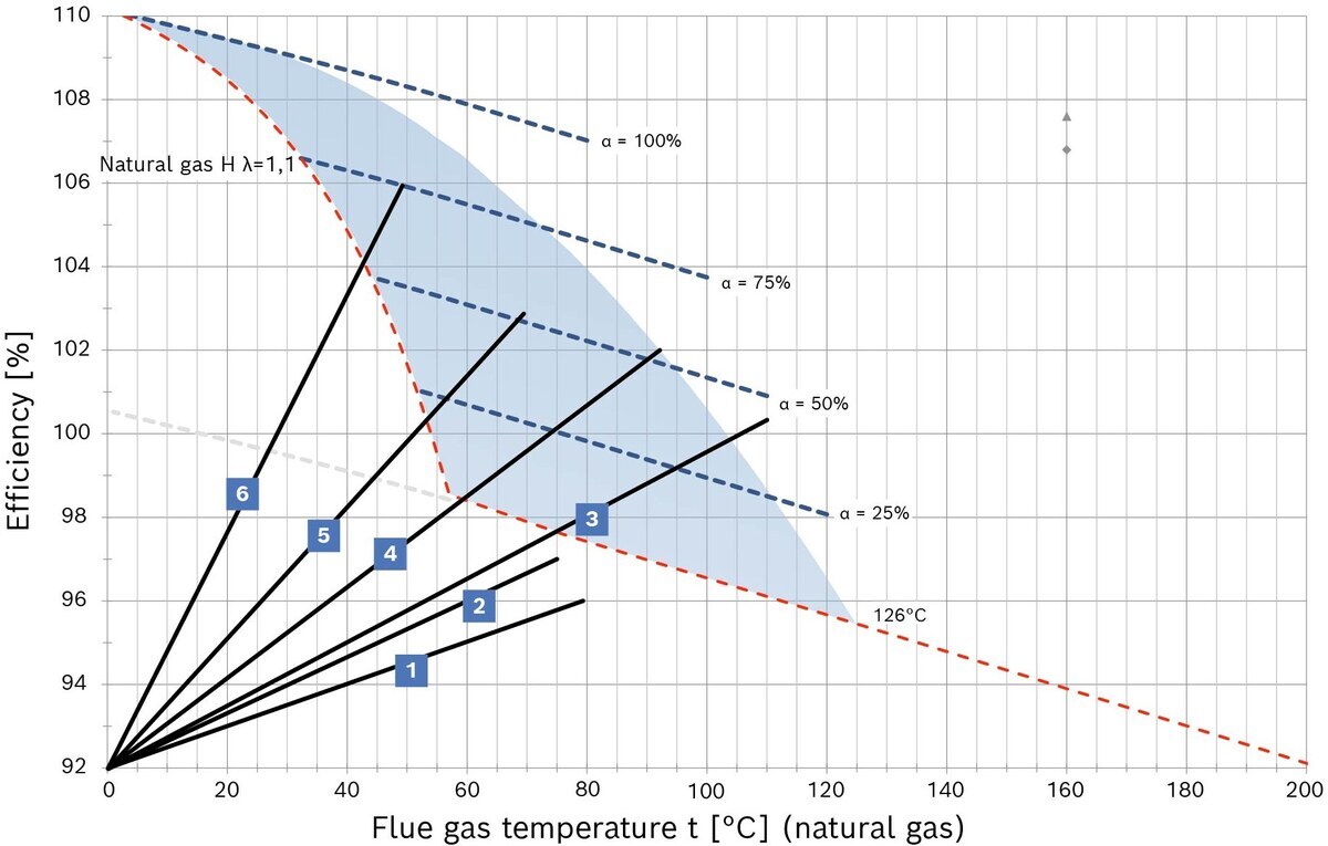
Pinch point diagram
Analysis graphically representing the efficiency range of flue gas heat exchangers with and without condensing technology. It clearly shows that the higher the condensation rate [α] in the flue gas, the higher the efficiency. Specifically, the difference between cases 1 and 2 compared to 3 and 4 is shown.
In cases 1 and 2, a non-condensing flue gas heat exchanger is used. Here, the efficiency is lower than with the flue gas heat exchanger with exhaust gas condensation, even though the flue gas temperature is lower.