
Safety technology
The safety of the system is primarily ensured by the correct operation, proper functioning and maintenance of the equipment and control systems of hot water boilers. To ensure safety at all times, including in the event of a failure of the standard control systems, automatic limiting devices are required on all hot water boilers. Together with the emergency off switches on the control panel and the escape doors, these are connected in series within the safety chain in the boiler control panel, so that if any of these triggers is activated, boiler operation is shut down and further danger is prevented.
If any of the limiting devices is triggered, the combustion process and, consequently, the heating of the boiler are shut down and locked. This lock can only be released manually on-site at the boiler. This is to ensure that, following any abnormal operating states, the boiler attendant has identified and eliminated the cause of the fault before the boiler is put back into operation.
Max. safety temperature limiterThe safety temperature limiter (TRZA+) is triggered if the maximum permissible temperature of the boiler or the downstream piping and heat consumption systems is exceeded, in order to reliably prevent the components from overheating or the system from operating outside the permissible temperature range.
In accordance with standards EN 12828 (applicable to equipment fitted to boilers under the Gas Appliances Regulation) and EN 12953 (applicable to equipment fitted to boilers under the Pressure Equipment Directive), every hot water boiler must be fitted with a safety temperature limiter.
-
Mechanical safety temperature limiter
Dual safety temperature limiter (i.e. a device comprising two separate measuring and switching systems). Due to the thermal inertia of the system, the flow temperature must be at least 10 K below the maximum permissible temperature (SCO). - Electronic safety temperature limiter
The electronic safety temperature limiter consists of a sensor and a switching amplifier for installation in the boiler control panel. Thanks to the measurement accuracy of the electronic safety temperature limiter, the delta between the safeguard temperature set via the SCO and the required flow temperature can be reduced to 7 K.
The safety pressure limiter min. (PRZA-) must activate in order to reliably prevent water from boiling away at the highest point of the entire hot water boiler system. The set minimum pressure level is determined by the design of the pressure-maintenance device. The safety pressure limiter min. can also be attached there.
Information about pressure-maintaining systems
Safety pressure limiter max.The safety pressure limiter max. (PRZA+) activates at 95 % of the maximum permissible operating pressure at the latest and switches off the boiler heating.
Safety valveIn the event of a failure of the safety pressure limiters, the safety valve must reliably prevent the pressure in the boiler from exceeding the maximum permissible level. For shell boilers, direct-acting, spring-loaded full-lift safety valves with closed spring housing and type F approval for liquids are used. Once the safety valve has opened, the pressure in the boiler must drop to approximately 10 % below the maximum permissible pressure so that the safety valve closes automatically under spring force. The piping leading from the safety valve must be routed directly into an expansion vessel. In the expansion vessel, the hot, pressurised water undergoes further evaporation, and the steam and water are separated. The steam pipe, which runs upwards, must be routed safely to the outside via the shortest possible route. The water is drained downwards, flowing openly into a cooling device and then into the sewer system.
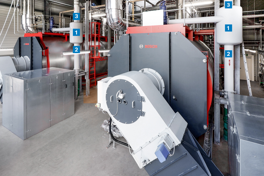
Hot water boiler system with correctly set safety valve
|
|
Expansion vessel with tangential intake |
|
|
Drain pipe for water open |
|
|
Expansion steam pipe via the roof |


The boiler’s heating surfaces must always be surrounded by water to ensure sufficient cooling. If the water level in the boiler drops so low that the heating surfaces are no longer submerged, there is a high risk of overheating and, in some cases, damage to the boiler.
To reliably prevent the heating surfaces from becoming submerged, level-limiter electrodes or mechanical level limiters can be used.
Level-limiter electrodeThe level-limiter electrode is a water level limiter with a “special design”. The level-limiting device is used to detect the minimum permissible water level (low water) in hot water generators. The level-limiting device works by exploiting the difference in conductivity between water and steam. When the level-limiter electrode is immersed or withdrawn, the device switches and, if necessary, triggers a fault shutdown.
The LW switching point is fixed by the installation location, the position of the level-limiter electrode and the length of the electrode rod, and can be adjusted. In the case of hot water generators, installation usually takes place in the supply flow adapter piece.
Mechanical level-limiterThe level-limiter is a safety device that uses magnetic transmission to transmit the movement of a float to a microswitch. It can be rotated through 360° and can be replaced without having to empty the system. As soon as the water level drops, the level-limiter activates the switch and locks into place once it has switched off. To put the system back into operation once the fault has been eliminated, it must be unlocked.
Flow monitorThe flow monitor is triggered if the volume flow falls below the level required to ensure adequate heat dissipation and adequate flow to the boiler’s temperature limiters and control devices.
The removal of the heat generated from the boiler is of the utmost importance, both for the operation of the system and for the boiler itself. If this heat dissipation is interrupted – for example, because there is no circulation in the boiler whilst the burner is running – heat builds up, which is not immediately detected as the temperature sensors are fitted in the supply flow adapter piece. This results in localised overheating, which can very quickly lead to damage to the boiler. The reason for this is that the network pressure, which is increased by the pressure maintenance provided on-site, is considerably higher than the boiling pressure associated with the flow temperature. This is known as subcooled boiling, which means that although vapour bubbles form, they collapse immediately after leaving the heating surface. Heat cannot be dissipated sufficiently via the vapour bubbles and must therefore be ensured by continuous water circulation. In a steam boiler, the situation is simpler as the liquid and steam phase are in equilibrium and, therefore, the vapour bubbles can dissipate the heat unhindered into the steam chamber. It is therefore essential that every hot water boiler with separate pressure-monitoring unit and a rapidly controllable burner system, regardless of the manufacturer and/or design, is fitted with a flow-through system. A minimum flow rate is not required under the Gas Appliances Regulation (EN 12828). It is only important that there is a flow. The minimum flow rate is defined as a speed of 0.15 m/s at the boiler socket. As the Gas Appliances Regulation does not stipulate any specific testing equipment for boilers, an operational signal from the boiler circuit pump is sufficient to ensure that water flows through the boiler and, consequently, that heat can be dissipated.
The issue described was addressed in the revision of standard EN 12953 Part 6 (Pressure Equipment Directive), and the list of required equipment for a hot water boiler was expanded to include a flow monitor. The flow monitor must meet the following requirements:- Approved in accordance with the Pressure Equipment Directive and EN 12953 Part 9 (Requirements for pressure relief devices)
- In accordance with EN 12953 Part 6: The use of impeller devices (impeller) and paddle devices is prohibited
Flame tube temperature monitoring (FTTM)
EN 12953 Part 3, Section 5.5, draws attention to national regulations which may require a temperature measurement system (i.e. flame tube temperature monitoring) for boilers, depending on the internal diameter of the flame tubes, the materials used for the flame tubes and the boiler output.
In Germany, the use of flame tube temperature monitoring is governed by the DK003 industry agreement.
FTTM required:- For the internal diameter of the flame tube
> 1,433 mm
- For heat output
> 14,000 kW (oil-fired)
> 18,200 kW (gas-fired)
In flame tube temperature monitoring, the wall temperatures are measured at several points. If the relevant limit values are exceeded at a thermocouple, the combustion system is shut down. The effect of deposits on the flame tube wall temperature can be estimated from the following figure. Depending on the load on the flame tube, these deviations may be more or less pronounced. The graphic is based on a heat flux density of q = 300,000 W/m², which is typical for shell boilers.
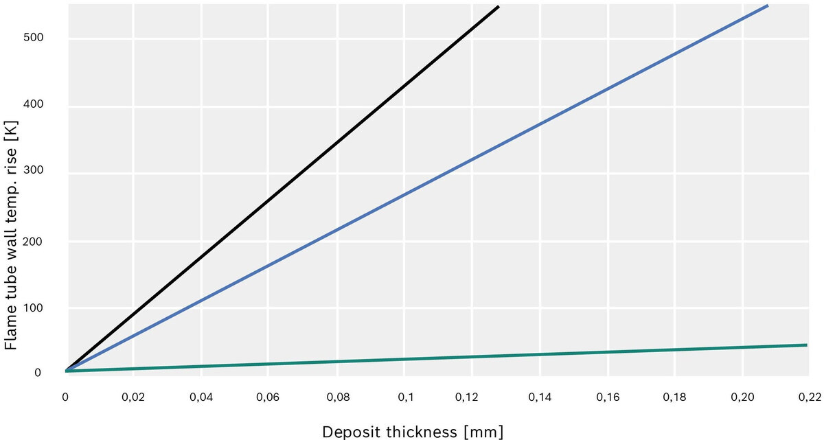
Temperature rise in the flame tube wall depending on the thickness of the coating
|
|
Silicate (pure substance) |
|
|
Film-forming agent |
|
|
Magnetite/hardness |


Emergency stop devices
Emergency stop buttons are installed on the boiler control panel and along the escape routes and these reliably shut down the boiler heating system in the event of any unforeseeable hazardous operating states.