
Increased efficiency of boilers and systems
Insulation
Losses due to conduction and radiation arise from the temperature differential between the medium in boilers, pipes and valves and the surrounding environment.
The amount of heat loss is mainly influenced by the size of the surface area, the medium and ambient temperature, and the type of insulation used.
Since these losses are not performance-related, they always occur, even during downtime, and are therefore present 365 days a year in systems or system components that are not shut down. Particularly in systems that are frequently operated at partial load, they have a negative effect on the annual efficiency of the boiler system.
Information about annual efficiency
In addition to the more complex examination with a thermal imaging camera, the “hotspots” with the greatest heat losses can usually be detected and eliminated simply by feeling for hot areas, visually inspecting the insulation or using a surface or radiation thermometer.
However, the surface temperature is only a limited measure of the amount of heat loss. Particularly when comparing different surface materials, a lower surface temperature sometimes indicates higher heat losses.
The reason for this lies in the radiation coefficient of the insulating surface. A high coefficient increases the heat losses but, at the same time, reduces the surface temperature. It is therefore advantageous to use a material with a low emission coefficient ε.
|
Example: |
|
|
Heat cylinder |
L = 3,600 mm, diameter = 1,700 mm |
|
Insulation |
D = 100 mm |
|
Medium temperature |
103 °C |
|
Surface material1) |
Emission coefficient ε |
Heat losses via container jacket |
Surface temperature |
|
Rolled aluminium |
0.05 |
627.5 W |
30.0 °C |
|
Oxidised aluminium |
0.13 |
635.5 W |
29.0 °C |
|
Galvanised sheet, bare |
0.26 |
645.5 W |
27.6 °C |
|
Galvanised sheet, outdated |
0.44 |
655.5 W |
26.3 °C |
|
Austenitic stainless steel |
0.15 |
637.2 W |
28.7 °C |
|
Aluminium-zinc plate, slightly oxidised |
0.18 |
639.7 W |
28.4 °C |
|
Non-metallic surface |
0.94 |
671.2 W |
24.2 °C |
List of emission coefficients, heat losses and surface temperatures for different surfaces
1) In accordance with VDI 2055 Sheet 1 Appendix A8
In existing systems, the greatest heat losses usually occur due to uninsulated valves, areas that are not re-insulated during system inspections or repairs, or thermal bridges formed when the insulating protective surface is moved.
By eliminating these “hotspots” in existing systems, a large proportion of conduction and radiation losses can be avoided without having to completely re-insulate the system. Measures taken on non-insulated areas of the entire system (e.g. boilers, pipes, valves, containers) represent one of the most economical energy-saving measures in existing systems.
The efficiency of the insulation can be improved by the following points.
Insulation thickness and surface
Increasing the insulation thickness may reduce the surface temperature and heat loss. However, it is important to choose a sensible, economical optimisation, since doubling the insulation thickness does not necessarily mean halving surface losses.
In addition to the insulation thickness and the medium temperature, the size of the surface also plays a decisive role in the total heat loss. Compact boiler designs, integrated flue gas heat exchangers and the resulting smaller insulation surface are advantageous here.
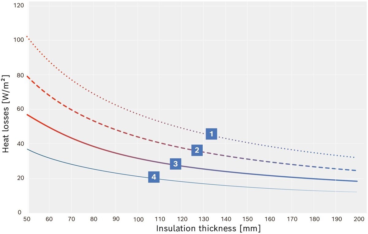
Heat losses via the insulated area of the container or boiler surface
|
|
Medium temperature: 150 °C |
|
|
Medium temperature: 125 °C |
|
|
Medium temperature: 100 °C |
|
|
Medium temperature: 75 °C |


The figure “Heat loss via the insulated area of the container or boiler surface” shows that, for a boiler room temperature of 20 °C, an insulation thickness of 100 mm and a medium temperature of 100 °C, heat loss of approx. 32 W/m² occurs.
With an insulation thickness of 150 mm, this is reduced by around 32 % to approx. 21.6 W/m². If the insulation thickness is increased to 200 mm, heat loss is reduced by 44 % to 17.9 W/m² compared to 100 mm insulation.
This only applies to insulated areas without thermal bridges. Since the losses across these jumpers may quickly exceed losses in the well-insulated cylindrical area, they must always be taken into account and minimised as far as possible.
Insulation of pipes
The continuous insulation of pipes carrying hot media is now mandatory in all system components for energy saving and occupational safety reasons (e.g. Energy Savings Order [Germany]). However, when deciding on a specific insulation thickness, it is not only the regulations that should be decisive but, above all, economic efficiency.
The following diagram can be used to determine both the absolute heat loss per metre of uninsulated pipe (left ordinate) and the savings factor of an insulated pipe (right ordinate) depending on the medium temperature, pipe diameter and insulation thickness.
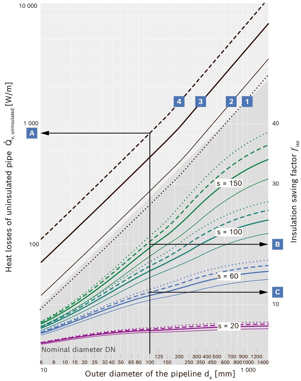
Savings factor due to insulation and heat losses from pipes
|
|
Medium temperature: 75 °C (. . . . . .) |
|
|
Medium temperature: 100 °C (_______) |
|
|
Medium temperature: 150 °C (_______) |
|
|
Medium temperature: 200 °C (- - - -) |
|
|
Insulation thickness s = 150 mm |
|
|
Insulation thickness s = 100 mm |
|
|
Insulation thickness s = 60 mm |
|
|
Insulation thickness s = 20 mm |
|
|
Heat loss in uninsulated condition |
|
|
Savings through insulation |
|
|
Savings through insulation |


The calculations for the above diagram “Savings factor through insulation and heat loss from pipes” are based on VDI 2055 Sheet 1: Uninsulated painted steel pipe, mineral wool insulation, aluminium rolled sheet insulation jacket, horizontal pipe, ambient temperature 20 °C.

For a flow line with a length of 200 m, increasing the insulation thickness from 60 mm to 150 mm results in savings of around €2,458 per year (assuming 8,000 operating hours and energy costs of 6 ct/kWh).
Every metre of uninsulated pipework costs around €400 per year here.
|
Example |
Insulation thickness |
Heat loss from the piping |
Total heat loss1) |
Absolute savings2) |
Percentage savings2) |
Cost savings2) |
|
A |
Uninsulated |
837.0 |
1,396,800 |
--- |
--- |
|
|
B |
s = 60 |
66.4 |
106,240 |
--- |
--- |
|
|
C |
s = 150 |
40.8 |
65,280 |
40,960 |
38.6 |
2,457.60 |
Potential savings through increased insulation thickness, using a flow pipe as an example
1) With a pipe length of 200 m and 8000 operating hours/year
2) With regard to the thickness of the insulation s = 60 mm
Minimisation of thermal bridges
Thermal bridges occur whenever metallic compounds with very good thermal conductivity break through the insulation. This is the case, for example, with nozzles, boiler supports or support consoles .
Particular care must be taken in the area of the insulation jacket to ensure that the penetrations required for functional reasons do not come into direct contact with the insulating protective jacket, as this would otherwise create thermal bridges at these points and lead to energy loss. Simply wrapping the connectors with insulating fabric can reliably prevent this. Elements that serve to improve stability and rigidity should be located within the insulation so that they do not conduct heat to the insulating protective jacket.
Spacers should not be used on cylindrical casing, as these also act as thermal bridges. The heat conduction from the hot boiler drum to the insulating protective jacket is prevented, and the thermal insulation of the insulating mat is effective across the entire surface.

Insulated inspection openings
Hot water boilers are subject to recurring internal inspections by the responsible monitoring organisations. The inspection openings, such as handholes, headholes or manholes, that are required for this mean that openings must be created in the insulation jacket. These openings are insulated and locked using removable insulating covers.
The inspection and cleaning openings on the flue gas collection chambers and heat exchanger housings are locked using the same insulation technology so that no increased radiation heat is lost through the inspection openings. Labels indicate inspection openings underneath.
Particularly after inspections or if the insulation covers have been removed for other reasons, care must be taken to ensure that the inspection openings are re-insulated.
The heat loss from an inspection opening with an area of approx. 0.5 m² that has not been resealed results in an energy loss of approx. 15 kWh per day at a medium temperature of 100 °C.
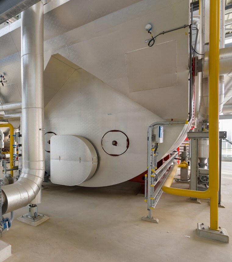
Removable insulation on inspection openings (UT-HZ with integrated flue gas heat exchanger)
Insulated valves
Hot water boiler systems contain numerous valves that are necessary for the operation and maintenance of the system. For installation or cost reasons, or due to different delivery limits, the insulation of valves or adapter flanges is still often omitted in new installations. Similarly, uninsulated valves are often found in existing systems.
However, these uninsulated areas cause a very high energy loss. The following table can be used to estimate the energy loss of an uninsulated valve.
|
Nominal pipe diameter |
DN 32 |
DN 40 |
DN 50 |
DN 65 |
DN 80 |
DN 100 |
DN 125 |
DN 150 |
DN 200 |
DN 250 |
|
|
Length in accordance with EN 558 Series 1 |
[mm] |
180 |
200 |
230 |
290 |
310 |
350 |
400 |
480 |
600 |
730 |
|
Uninsulated heat loss |
[W] |
44 |
54 |
75 |
114 |
139 |
193 |
262 |
367 |
574 |
858 |
|
Insulated heat loss |
[W] |
6 |
6 |
7 |
9 |
9 |
11 |
14 |
19 |
28 |
40 |
|
Savings |
[W] |
38 |
48 |
68 |
105 |
130 |
183 |
248 |
349 |
546 |
818 |
|
Heat loss at 8,000 Bh/a |
[kWh/a] |
304 |
384 |
541 |
842 |
1,037 |
1,462 |
1,982 |
2,788 |
4,367 |
6,544 |
|
Savings at 8.5 pence/kWh |
[€/a] |
26 |
33 |
46 |
72 |
88 |
124 |
168 |
237 |
371 |
556 |
Heat losses and running costs of uninsulated valves (medium temperature 100 °C, ambient temperature 20 °C)
Notes on the table:- Medium temperature 100 °C, ambient temperature 20 °C
- Calculation of pipeline heat losses in accordance with VDI 2055 Sheet 1
- Conversion of heat losses from pipes into heat losses from valves with a length factor of 1.6 for insulated valves and a length factor of 2 for uninsulated valves. (This results in significantly more conservative heat losses for uninsulated valves and lower savings than if the calculation were carried out entirely in accordance with VDI 2055 Sheet 1.)
- Valve length in accordance with DIN EN 558 Series 1
- Calculated with an insulation thickness of 100 % (insulation thickness = DN to DN 100; insulation thickness = 100 mm from DN 125)
The reduction in heat loss through the insulation of valves is approximately 193 W at a medium temperature of 100 °C and a valve with a nominal diameter of DN 100. With a nominal diameter of DN 150, approximately 367 W. With the cost of insulating a valve ranging from €150 to €300, the investment in insulation pays for itself within a year.
Since valves are required in many places in a complete heating or hot water system, the total potential savings from insulating the valves amount to an average of around 1 – 5 % of fuel consumption.