
Equipment and control
The minimum requirements for the operation and safety equipment of hot water boilers are set out in DIN EN 12953-6. This includes all main shut-off valves on the pipes that are connected to the boiler, safety devices to prevent excessive pressure, temperature and water shortages, the heating equipment, and all the valves/fittings and measuring devices required for operation and control. All such equipment must be approved in accordance with the Pressure Equipment Directive.
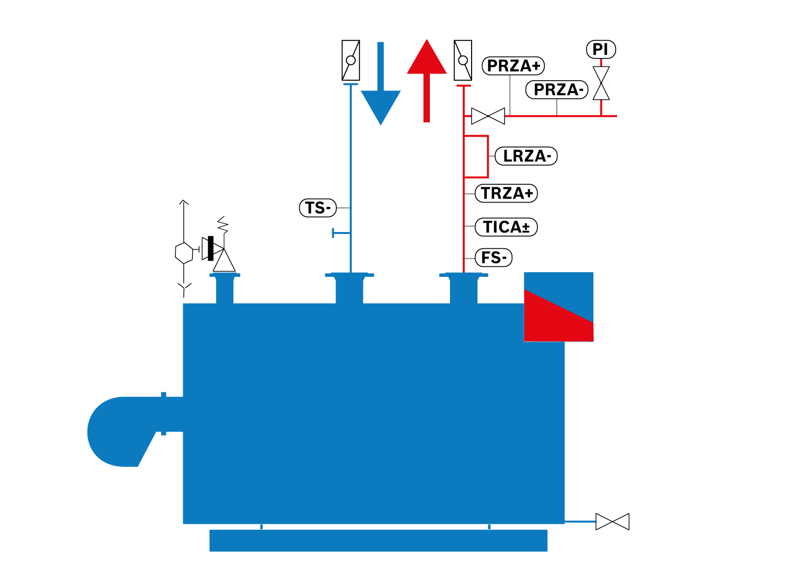
Basic equipment for a hot water boiler
- Shut-off valve for flow and return
- Full-lift safety valve (pressure safeguard)
-
Supply flow adapter piece with
- Temperature limiter (TRZA+)
- Flow monitor (FS-)
- Temperature controller (TICA+-)
- Level limiter (LRZA-)
- Manometer manostat pipe with shut-off valve, pressure limiter max. (PRZA+), pressure limiter min (PRZA-), manometer (PI)
-
Return flow adapter piece with
- Temperature monitor (TS-)
- Connection for safety expansion line
- Injector device for internal temperature increase
- Circulation pump
- Return temperature control
- Flue gas temperature indicator (TI)
- Burner
Performance regulation
The performance regulation for the boiler’s heat output takes place via the flow temperature that is required in the heat consumer.
If consumers extract more heat and the flow temperature at the boiler outlet drops, the performance regulation increases the heat supply or the burner’s output. It is important to note that the burner/boiler system is a slow-responding system. All control devices and control elements that are connected to this system are coordinated to this behaviour in order to prevent control fluctuations as well as unnecessary stress and faults at the boiler. Provided that the output is reduced evenly, the control system is correctly adjusted and the burner is infinitely variable, the burner automatically adjusts its heat output to the level required to meet the current heat demand, and the flow temperature is maintained at a constant level, with only minor deviations from the setpoint.
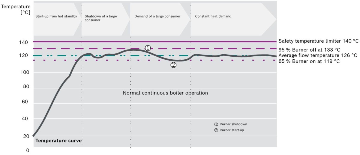
Diagram showing the temperature profile with burner set points for hot water boilers
Depending on the heat output required by the consumer, the boiler system’s combustion process adjusts in accordance with the diagram shown above. Water is the primary heat transfer medium used in the heating circuit. However, the required heat can only be transferred to the consumer if a corresponding volume flow is circulated. This is calculated using the following formula:

In principle, it can be deduced from this that the boiler spread, in conjunction with the boiler capacity, determines the required volume flow. In principle, there are two types of circulation pumps.
Variable-speed pumpsIf the circulation flow in the consumer network drops, the boiler pumps reduce the flow rate at the heat generator and, at the same time, lower their power consumption. By regulating the boiler water flows, unnecessary burner modulation is avoided. The reference peaks have been smoothed accordingly.
Fixed pumpsThe circulation pumps deliver a constant volume flow or operate at 100 % output in accordance with the pump characteristic. Depending on the boiler system’s application and the heat demand on the consumer side, the burner’s modulation is less than optimal when compared to a variable-speed pump.
Return temperature safeguard
To reliably prevent excessive thermal stresses in conventionally fired boilers, care must be taken to ensure that the maximum temperature spread between the flow and return temperatures is not exceeded. It is also important that the temperature of the flue gas does not fall below the condensation temperature inside the boiler, in order to prevent water forming in the flue gas and, consequently, corrosion.
To this end, the permissible return temperature in the boiler is limited to a minimum value. The minimum return temperatures are 50 °C for UT-L, UT-M and UT-H boilers, and 60 °C for UT-HZ boilers.
However, as lower temperatures may occur in the heating distribution network or during start-up, the return flow temperature may need to be raised to these minimum values.
The maximum temperature spread between the flow and return pipes at the boiler is also limited. For UT-L and UT-M boilers, the maximum spread is 50 K; for UT-H and UT-HZ boilers, it is a maximum of 40 K. If there are significant temperature spreads coming from the heat consumers, the return temperature to the boiler must also be increased in these systems.
Depending on the boiler’s heat output and the water volume flow within the boiler, various systems are available for this purpose.
Return flow temperature boosting with a pumpThis type of wiring is appropriate where on-site network pumps are already in place and are also responsible for dissipating heat from the boiler, e.g. where only supply and return manifolds are present on the network side, or in district heating systems with central network circulation pump stations. The lifting pump is designed according to the network return temperature or the minimum boiler water flow rate. The pump’s flow rate is designed to ensure that enough water is added from the supply line to achieve the boiler return temperature specified for the boiler in the project. The lifting pump always runs when the measured temperature at the return (before mixing) is less than the specified setpoint.
The variable-speed lifting pump increases or decreases its speed when the boiler return temperature falls below or rises above the setpoint. This keeps the return temperature at the set minimum value. This means that, compared to an on/off pump, electrical energy can be saved.
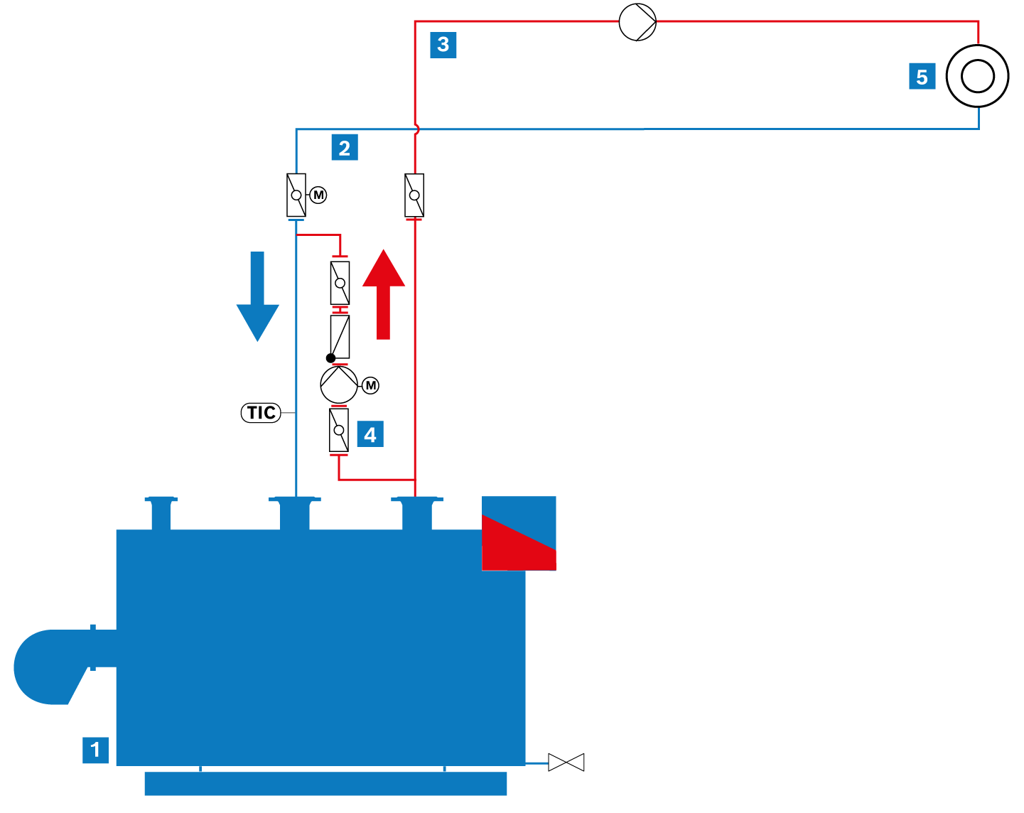
Return flow temperature boosting with variable-speed pump
|
|
Hot water boiler |
|
|
Return |
|
|
Flow |
|
|
Return temperature boosting |
|
|
Heat consumer |


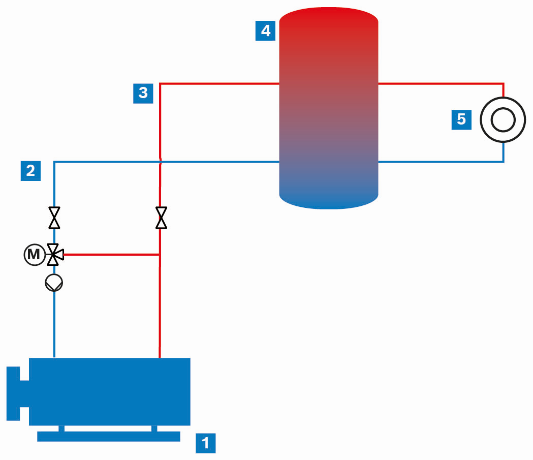
This type of circuit is appropriate for conventionally fired boilers where a low loss header or a manifold without differential pressure is installed. The boiler circuit pump ensures that the entire volume of water is circulated on the generator side. When designing the boiler circuit pump, water-side resistance to the low loss header must be taken into account.
The three-way valve regulates the boiler return temperature by mixing in hot flow water while reducing the water volume supplied to the system.
The variable-speed boiler circuit pump ensures that the quantity of heat delivered from the boiler to the network is regulated according to demand. The return flow temperature in the network (directly upstream of the three-way valve) can be used as a proxy for the quantity of heat extracted from the system by the consumers. If the return temperature in the network drops, the consumers draw more energy from the system than is being replenished by the boilers. The speed of the boiler circuit pump is then increased, which also increases the heat output into the network (as a direct consequence, the boiler increases its output to maintain the flow setpoint temperature). If, on the other hand, the network return temperature increases, less heat is extracted from the network. Reducing the pump speed can save electricity.
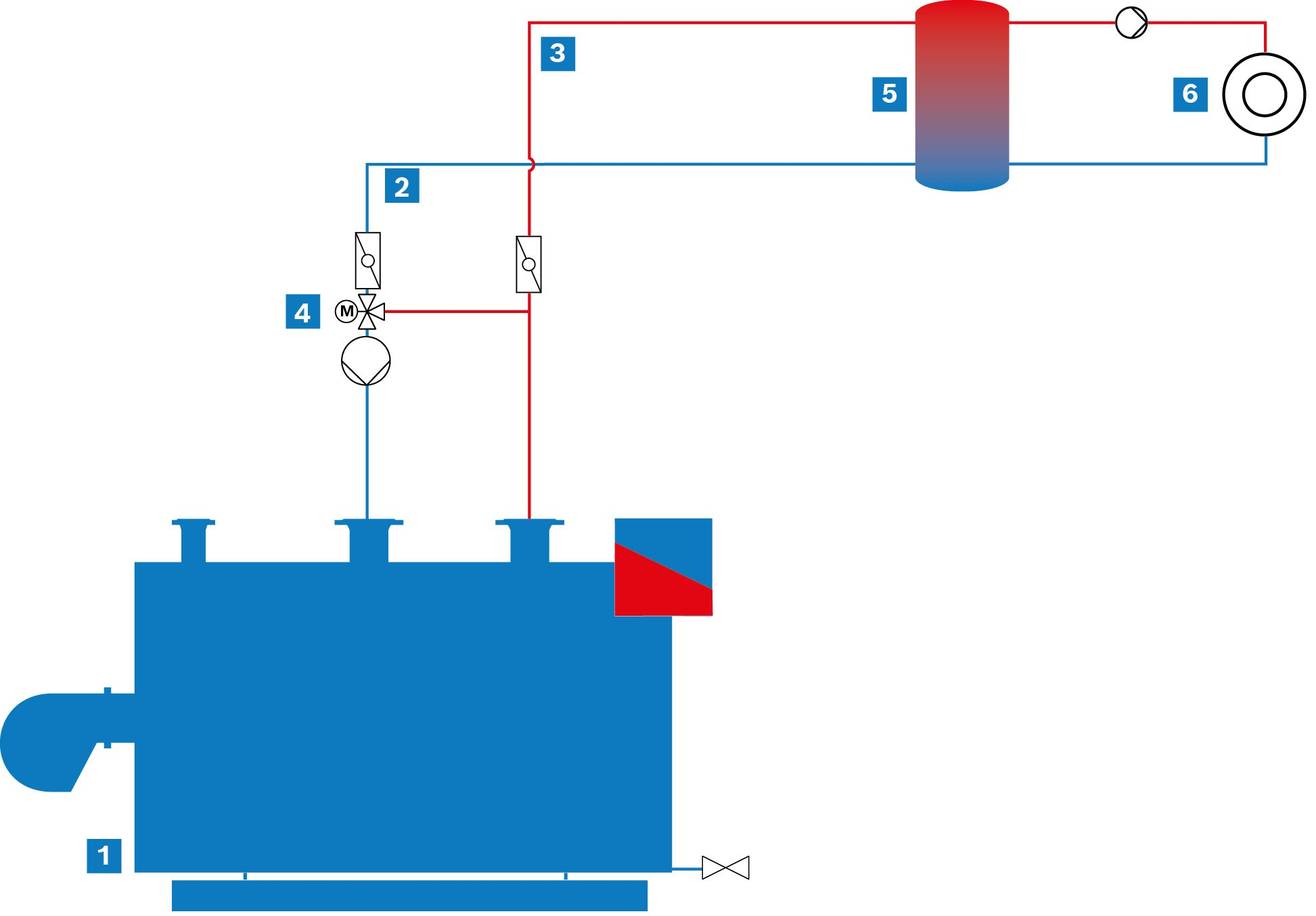
Diagram of a hot water boiler system with return temperature maintenance
|
|
Hot water boiler |
|
|
Return |
|
|
Flow |
|
|
Return temperature maintenance |
|
|
Heat cylinder with hydraulic separation |
|
|
Heat consumer |


When using condensing boilers, particular attention must be paid to the integration of the return temperature protection. Raising the return temperature upstream of the stainless steel condensing heat exchanger would negate the benefits of the condensing technology and therefore lead to higher fuel costs. Combining this with solar thermal energy is particularly suitable for protecting the return temperature. Particularly in systems with low return temperatures, the cold return water from the heating circuit is routed through the solar cylinder. This heats up in the process, thereby reducing fuel consumption even when there is little sunlight.
Flow temperature protection with three-way control valve (ELHB)
- Ensuring the required flow temperature at the boiler outlet
- Ensuring adequate flow through the heating bundle
Unlike conventionally fired boilers, return temperature protection is not required for electrically powered heating and hot water boilers, as there is no risk of condensation forming due to the absence of flue gases. Consequently, the minimum water inlet temperature for electric boilers is not 50 °C or 60 °C, as is the case with conventional boilers, but just 5 °C.
Nevertheless, even for electrically powered boilers, there are limits on the temperature spread between the boiler flow and return. These are defined as a maximum of 40 K and a minimum of 20 K, in order to, on the one hand, ensure that the minimum water volume in the heating bundle required for heat dissipation is not undershot and, on the other hand, prevent the flow speed from becoming too high when the temperature spread is lower.
ELHB hydraulic electric hot water boiler
|
|
Electric hot water boiler |
|
|
Return |
|
|
Flow |
|
|
Heat cylinder with hydraulic separation |
|
|
Heat consumer |