
Low loss header
The technical requirements of the heat generators for safe and economical operation differ from the technical requirements that heat consumers place on the system.
The low loss header, as a system component in heating and hot water boiler systems, separates the requirements of the heat generator from those of the heat consumer. It balances out the differences in volume flows between the heat generator and the heat consumer under various operating states.
This means that both sides can be operated hydraulically or thermally independently from each other.
When designing the system, ensure that all boundary conditions affecting generators and consumers, such as summer and winter loads, are taken into account. At maximum volume flow on both the generator and consumer sides, the flow speed (in the case of internal balancing) in the low loss header must remain below 0.1 m/s. This restriction ensures that the low loss header fulfils its primary function ofpressure isolation without pressure loss and also enables air separation.
Consumer requirements- Heat output control for consumers from 0 – 100 %
- At the heat consumer, both the heat quantity and the temperature difference vary as required
- The flow temperature at the consumer unit can be fixed or variable (e.g. weather-compensated)
- Return temperature at the consumer:
- Varies depending on the application
- It is advisable to keep the return temperature as low as possible to maximise the efficiency of heat recovery systems or heat pumps
- Low return temperatures, resulting in a large temperature spread between the flow and return, reduce the electrical power consumption of the circulation pumps
Heat generator requirements
- Performance regulation:
- Infinitely variable power control from 0 – 100 % is only available for electrically powered hot water and heating boilers
- All other heat generators, such as hot water boilers, central heating boilers, combined heat and power units, heat pumps and biomass boilers, have a minimum output that must not be fallen short of
- Maximum temperature spread between the flow and return:
- Hot water and heating boilers 40 – 50 K
- Heat pumps: 10 K depending on the application, or 30 – 60 K for multi-stage systems
- CHP units usually 20 K
- Minimum temperature spread between the flow and return:
- Hot water and heating boilers 10 – 20 K
- Heat pumps: 10 K depending on the application, or 30 – 60 K for multi-stage systems
- CHP units usually 10 K
- Minimum circulation quantity:
- Safe heat dissipation from the heat generators
- Safe air intake for temperature controllers and limiting devices
- Maximum circulation quantity:
- Usually defined by the design
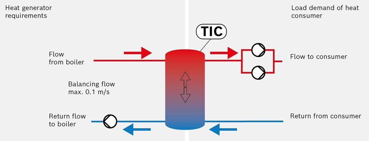
Basic functionality of a low loss header
Operation of heat generators only
The low loss header is flowed through from top to bottom. The temperatures in the return pipe to the boiler increase.
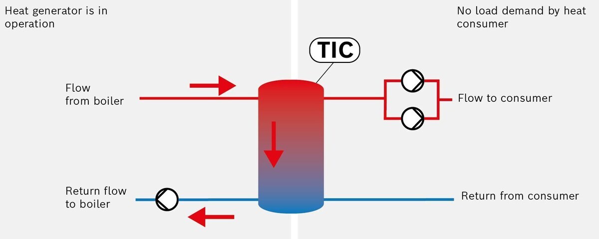
Operation of the low loss header on the heat generation side
Operation of heat consumers only
The low loss header is flowed through from bottom to top. The temperatures in the flow to the heat consumer drop.
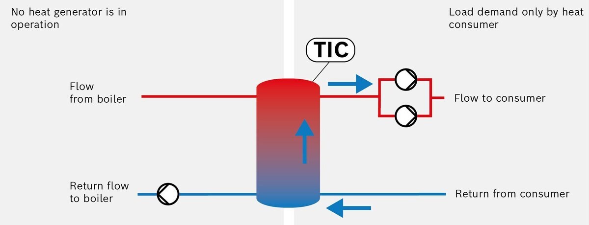
Operation of the low loss header on the heat consumer side
Examples of the simultaneous operation of heat generators and heat consumers
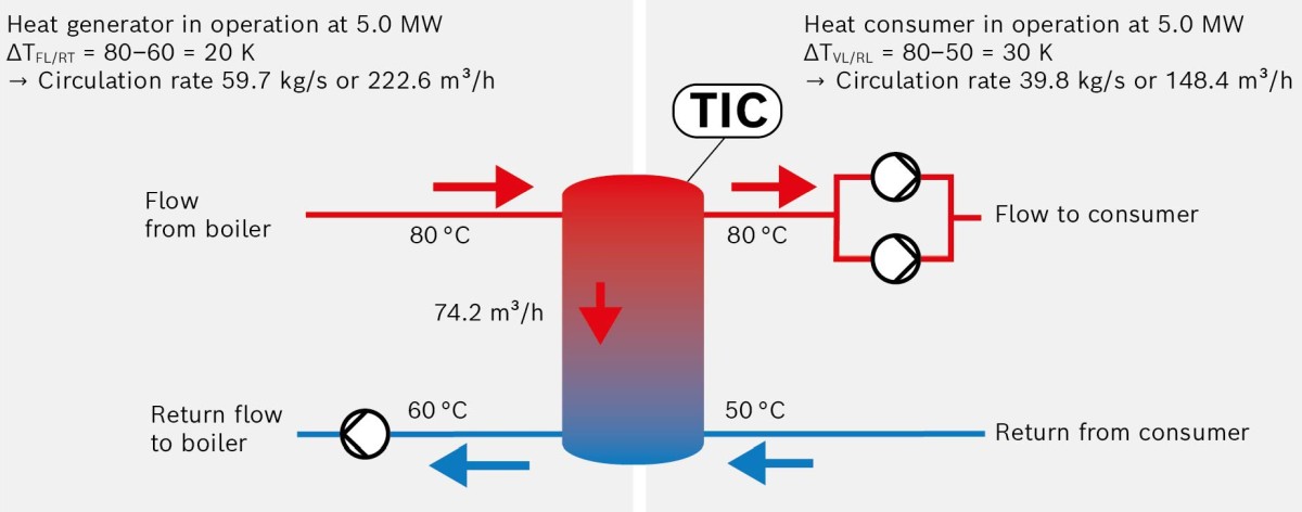
Simultaneous operation of heat generators and heat consumers with a boiler capacity of 5 MW
The return temperature to the boiler is increased by 10 K, as the volume flow is lower despite the boiler operating at the same output, due to the greater temperature spread on the heat consumer side.

Impact of the flow temperature with higher heat extraction on the consumer side
In this operating state, the flow temperature to the consumers is reduced to 68 °C by the inflow of cold return water from the mains.
If there are lower pressure losses in the common connecting pipes (boiler flow and return) to the hydraulic separator, multi-boiler systems can also be integrated hydraulically independently.
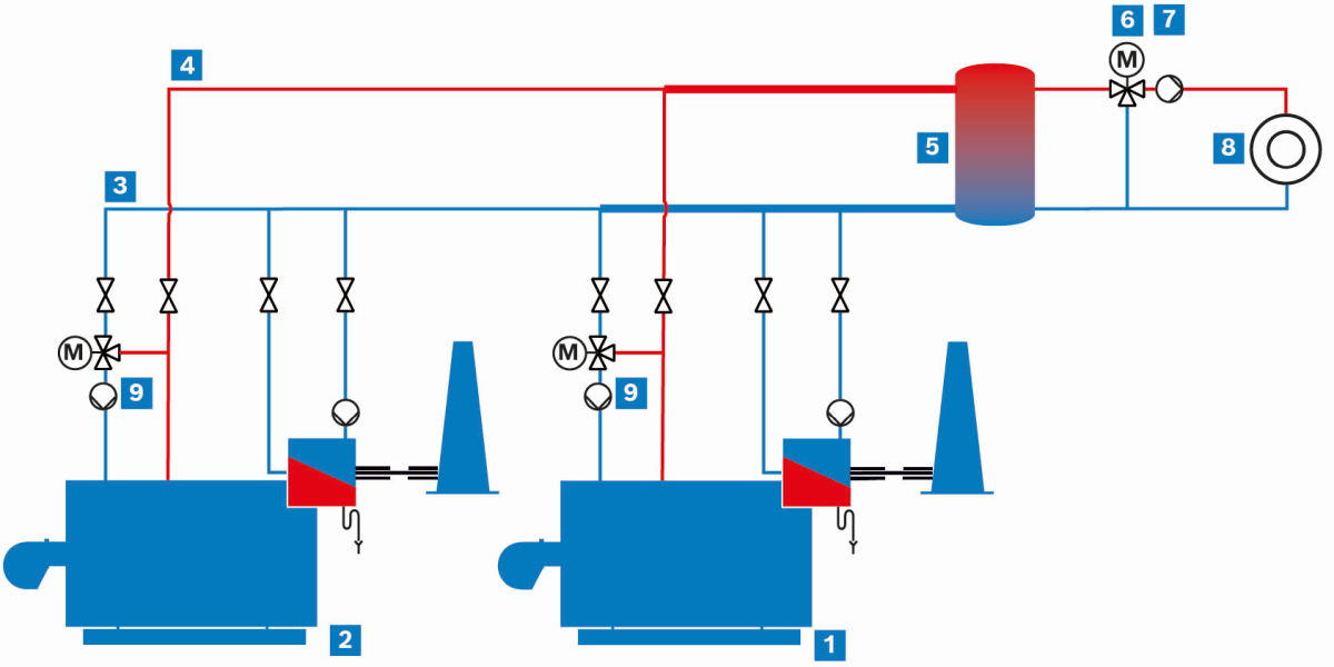
Hot water system as a multi-boiler system with low loss header
|
|
Hot water boiler 1 |
|
|
Hot water boiler 2 |
|
|
Return |
|
|
Flow |
|
|
Low loss header |


|
|
Three-way valve for the flow temperature control |
|
|
Mains-powered circulation pump |
|
|
Heat consumer |
|
|
Boiler circuit pump |


