
Combustion installations for liquid fuels
The following section describes the key terms and distinguishing features of combustion systems and the necessary equipment.
Pressure atomiser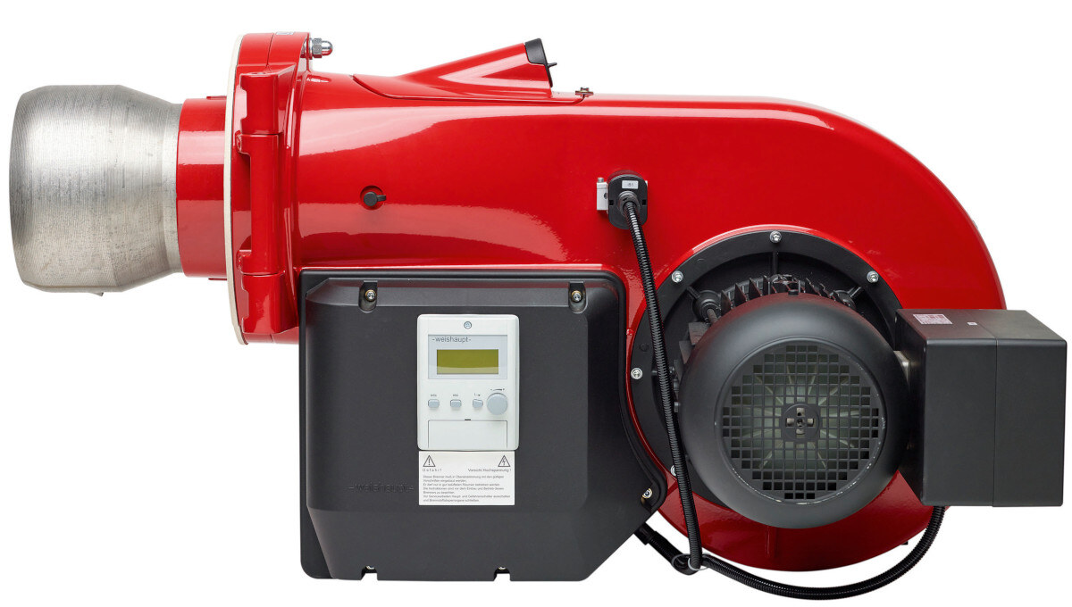
Oil burner pressure atomiser (Image: Weishaupt)
In pressure atomisation, the oil is passed through a nozzle and finely atomised as it enters the combustion chamber. The required supply pressures in the oil supply are 6 – 30 bar. As the oil jet emerges from the nozzle, fine oil droplets form, creating a large reaction cross-section. For this to be the case, the viscosity of the fuel must be within the range of 3–6 mm2/s. If this is not the case at ambient temperature, the oil must be preheated.
The burner can be controlled in various ways. In staged burners, several nozzles are built in to the burner tip. Depending on the output requirement, nozzles are activated or deactivated by actuating solenoid valves. Burners with up to three nozzles are available.
Return-nozzle burners are used to provide infinitely variable power control. To this end, a valve in the fuel oil return line regulates the amount of fuel supplied to the combustion chamber. This valve is controlled in conjunction with the position of the combustion air damper.
Rotary atomiserThe liquid fuel is supplied at low pressure to a conical atomising cup via a rapidly rotating hollow shaft. On this, the oil film that forms spreads out towards the rim of the cup, which widens towards the combustion chamber. Due to centrifugal force, the film of oil breaks away from the rim of the cup and forms fine droplets of oil, which are flung into the combustion chamber with a spinning motion.
Part of the combustion air is directed into the cup, whilst the rest flows in an annular gap around the cup, usually with a counter-rotating swirl. The addition and distribution of combustion air affects the flame pattern. This results in the oil being thoroughly mixed with the combustion air.
The main advantage of the rotary atomiser is that it is less dependent on the viscosity of the fuel than a pressure atomiser. This means that even fuels of fluctuating quality can be burned safely. The rotation of the cup can also be monitored to ensure low-emission combustion without the formation of CO and soot.
Fuel oil
The fuel oil that is used as fuel is a mixture of various hydrocarbon compounds. The exact composition may vary depending on the origin and refining process of the fuel oil. In general, fuel oil consists of the following main components:
- Aliphatic hydrocarbons: These include linear or branched hydrocarbon chains, such as alkanes (paraffins) and alkenes (olefins). They are the main components of fuel oil and are used as fuel for heat generation.
- Aromatic hydrocarbons: These include ring structures such as benzene, toluene and xylenes. Aromatic compounds contribute to the energy density of the fuel oil, but may also influence the type and quantity of emissions.
- Sulphur compounds: Fuel oil may contain varying amounts of sulphur, which produces sulphur dioxide (SO2) during combustion. The fuel oils most commonly used today generally have a low sulphur content (< 0.1 %) in order to reduce their environmental impact.
- Nitrogen compounds: The nitrogen-containing compounds that are present in fuel oil and their combustion behaviour influence the formation of environmentally harmful nitrogen oxides (NOₓ).
- Oxygen-containing compounds: If the product contains oxygen-containing compounds, such as alcohols and ethers, these may affect its combustion properties.
The exact composition and quality of fuel oil may vary from region to region. However, most fuel oils are formulated to burn efficiently and in an environmentally friendly manner, with particular attention paid to low sulphur and nitrogen content and improved combustion output.

Oil pans must be provided beneath modules and threaded connections in the oil pipe to catch any leaks. In addition, local regulations may apply that specify the further use of oil pans.
Other liquid fuels
A fuel analysis is required for liquid fuels that do not comply with the standard.
The fuel analysis must include at least the following information:- Net calorific value [kWh/kg]
- Kinematic viscosity at t = 20 °C [mm2/s]
- Kinematic viscosity at t = 100 °C [mm2/s]
- Density [kg/m3]
- Flash point [°C]
- Max. sulphur content in the fuel [%]
- Water content [%]
- Ash content [%]
- Coke residue [%]
- Total contamination [mg/kg]
Oil supply
The choice of a suitable oil supply system depends on various factors:- Distance and elevation difference from the extraction point to the consumer
- Installation costs
- Reliability and maintenance requirements
- Combustion system
- Regional or country-specific regulations
Regional regulations may specify the type of oil supply system that may be used. In addition, local authorities may impose requirements based on the location of the installation (e.g. installation within a water protection area).
Ring line system
The ring line system is a common method of oil supply that offers a number of advantages in terms of reliability and efficiency.
Functionality
A ring main with a separate pump is installed. The individual burners are connected to the ring main. The connection to the ring main is made via a gas-air separator or an oil circulation device.
- Stable supply: Continuous circulation ensures a stable supply of oil and prevents the formation of air bubbles
- Greater distance: The system can cope with greater distances between the tank and the burner
- Greater reliability: The oil recirculation makes the system more robust and less prone to faults
- More complex installation: The installation is more complex due to the additional piping
- Higher risk of leaks: More piping means a higher risk of leaks
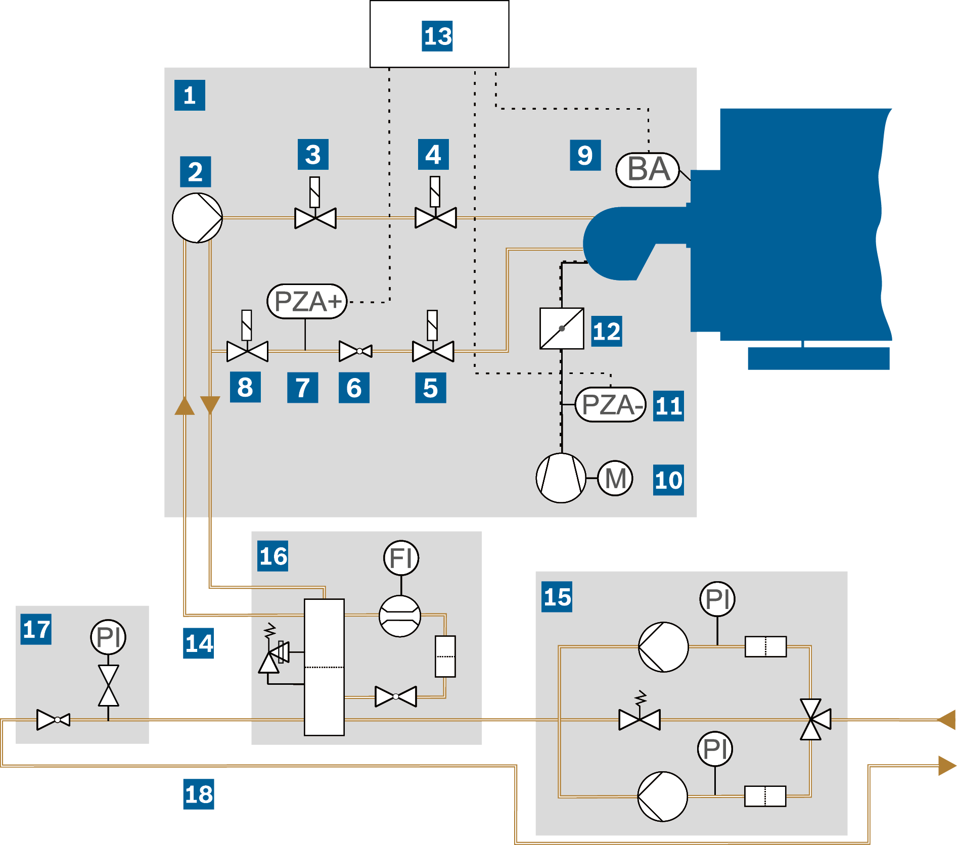
Sample illustration of a light fuel oil fired system with a pressure atomiser burner (oil pans required)
|
BRZA- |
Flame detector |
|
FI |
Flow rate indicator |
|
FI |
Pressure indicator (pressure gauge) |
|
PZA- |
Protection against air shortage |
|
PZA+ |
Maximum pressure limiter |
|
|
Burner |
|
|
Burner oil pump: Generates the pressure required for atomisation, ranging from 12 to 30 bar |
|
|
Solenoid valve: First shut-off of the fuel supply in the oil supply line |
|
|
Solenoid valve: Second shut-off of the fuel supply in the oil supply line |
|
|
Solenoid valve: First shut-off in the oil return line |


|
|
Oil pressure regulator: Adjustment of the oil pressure at the burner return nozzle depending on the required load |
|
|
Maximum pressure limiter: Shuts down the combustion installation if the oil pressure is too high |
|
|
Solenoid valve: Second shut-off in the oil return line |
|
|
Flame detector: Shuts down the burner if stable combustion has not been established in the combustion chamber after a start-up interval |
|
|
Fan: Combustion air supply |


|
|
Protection against air shortage: Cut-out of the combustion system in the event of low discharge pressure from the combustion air fan |
|
|
Air damper: Control of the fuel-to-air ratio |
|
|
Solenoid valve: Second shut-off in the oil return line |
|
|
Oil return pipe |


|
|
Oil supply module, OSM |
|
|
Oil circulating module, OCM |


|
|
Oil pressure control module, ORM |

|
|
Oil ring line |

Single-pipe system
The single-pipe system is one of the simplest and most common methods of oil supply. It has several advantages, including a lower risk of leaks and simpler installation.
Functionality
A single-pipe pump runs from the oil tank to the boiler burner, conveying the oil from the tank to the burner. The burner oil pump draws oil from the oil circulation module.
- Lower risk of leaks: As only one pipe is used, the risk of leaks is lower.
- Simpler installation: Fewer pipes mean simpler installation.
- Simple maintenance: Fewer components mean simpler maintenance.
- Formation of air bubbles: There is a risk that air bubbles may form in the pipe, which may lead to operating faults.
- If the boiler is operated at low load for a prolonged period, the oil in the internal return line of the single-pipe pump may overheat.
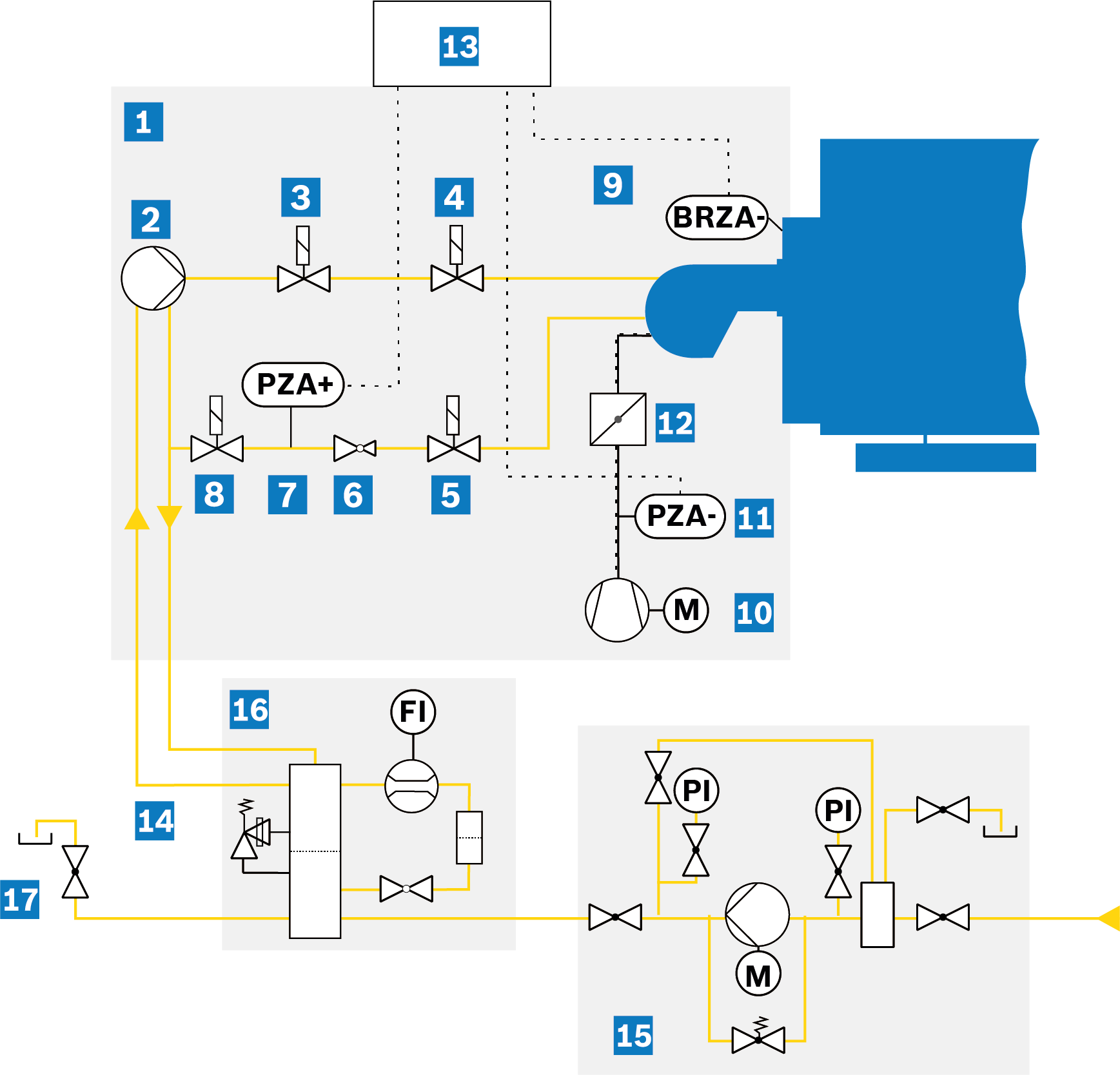
Sample illustration of a light fuel oil fired system with single-pipe system to the oil supply (oil pans required)
|
|
Burner |
|
|
Burner oil pump: Generates the pressure required for atomisation, ranging from 12 to 30 bar |
|
|
Solenoid valve: First shut-off of the fuel supply in the oil supply line |
|
|
Solenoid valve: Second shut-off of the fuel supply in the oil supply line |
|
|
Solenoid valve: First shut-off in the oil return line |
|
|
Oil pressure regulator: Adjustment of the oil pressure at the burner return nozzle depending on the required load |
|
|
Maximum pressure limiter: Shuts down the combustion installation if the oil pressure is too high |
|
|
Solenoid valve: Second shut-off in the oil return line |
|
|
Flame detector: Shuts down the burner if stable combustion has not been established in the combustion chamber after a start-up interval |
|
|
Fan: Combustion air supply |
|
|
Protection against air shortage: Cut-out of the combustion system in the event of low discharge pressure from the combustion air fan |
|
|
Air damper: Control of the fuel-to-air ratio |
|
|
Burner manager/burner safety chain |
|
|
Oil return pipe |
Oil supply
|
|
OSM oil supply module for single-pipe system |
|
|
Oil circulating module, OCM |
|
|
Venting |
Negative pressure system
The negative pressure system, also known as a vacuum system, is used in very few applications for oil supply in smaller combustion systems (usually multi-stage burners). The basic requirement is that the burner oil pump is designed for suction operation (not all burner oil pumps are capable of this). When dimensioning the suction line from the burner to the tank, care must be taken to ensure that no negative pressure greater than 0.4 bar occurs under full load.
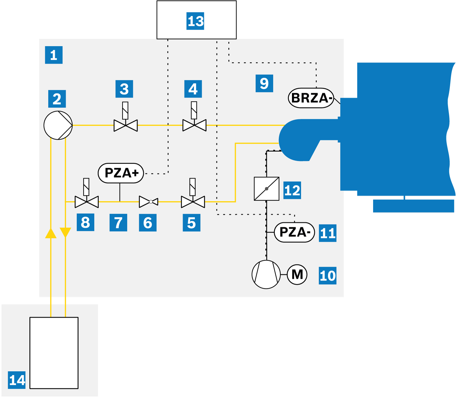
Sample illustration of a light fuel oil fired system with negative pressure system to the oil supply (oil pans required)
|
|
Burner |
|
|
Burner oil pump: Generates the pressure required for atomisation, ranging from 12 to 30 bar |
|
|
Solenoid valve: First shut-off of the fuel supply in the oil supply line |
|
|
Solenoid valve: Second shut-off of the fuel supply in the oil supply line |
|
|
Solenoid valve: First shut-off in the oil return line |
|
|
Oil pressure regulator: Adjustment of the oil pressure at the burner return nozzle depending on the required load |
|
|
Maximum pressure limiter: Shuts down the combustion installation if the oil pressure is too high |
|
|
Solenoid valve: Second shut-off in the oil return line |
|
|
Flame detector: Shuts down the burner if stable combustion has not been established in the combustion chamber after a start-up interval |
|
|
Fan: Combustion air supply |
|
|
Protection against air shortage: Cut-out of the combustion system in the event of low discharge pressure from the combustion air fan |
|
|
Air damper: Control of the fuel-to-air ratio |
|
|
Burner manager/burner safety chain |
|
|
Oil tank |
Oil supply module, OSM
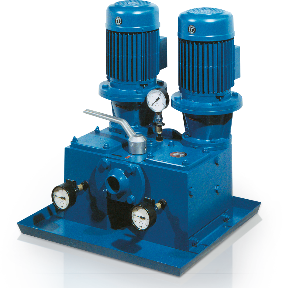
Oil supply module (oil pan required)
| PI | Manometer |
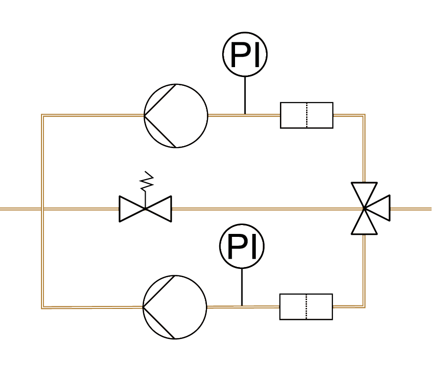
Oil supply module graphic
The oil supply module pumps the fuel from the oil storage tank located outside the boiler house via the oil supply system (the single-pipe system or the oil ring line) to the individual oil circulation devices, which supply each oil burner separately.
It is pre-assembled as a single or double station, with all valves/fittings housed in an oil collection tray, for simple installation into the oil supply system. The double station provides 100 % reserve for operational reliability, even when the oil filter is changed.
Attention must be paid to the NPSH values (i.e. the required positive suction head) of the various pumps in the ring main and to the theoretical suction head.
Oxygen and gases that are present in small quantities in fuel oil can be released if the negative pressure is too high (> 0.4 bar). This has the same effect as if there were air in the fuel oil pipe. The oil supply module can therefore be used with light fuel oil up to a maximum suction-side negative pressure of 0.4 bar.
Oil pressure control module, ORM
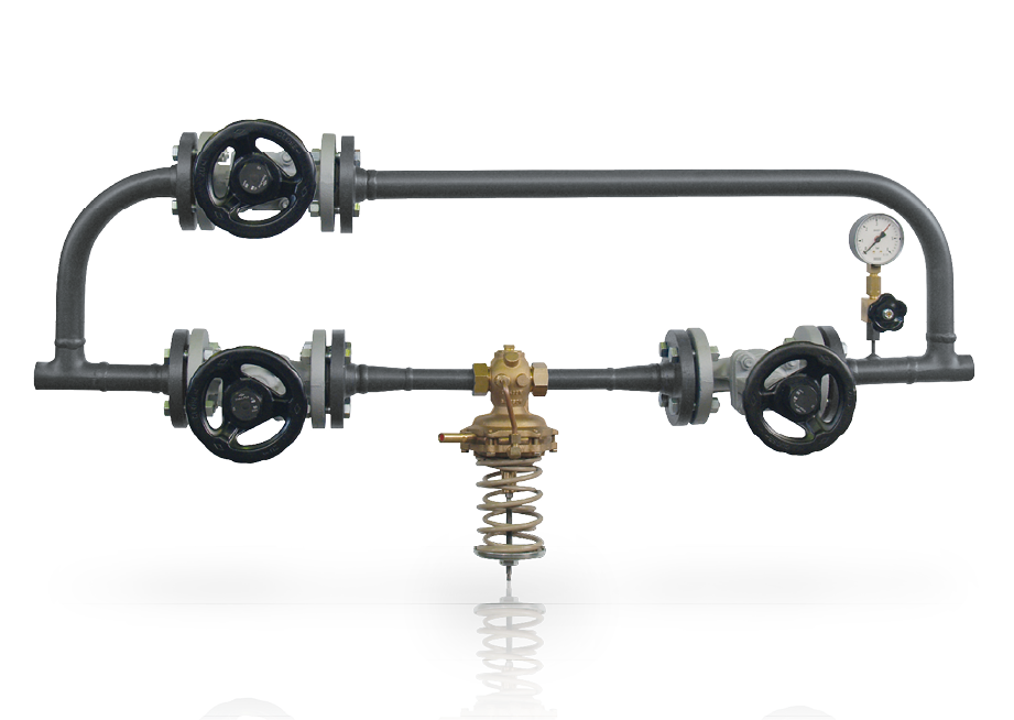
Oil pressure control module (oil pan required)
| PI | Manometer |
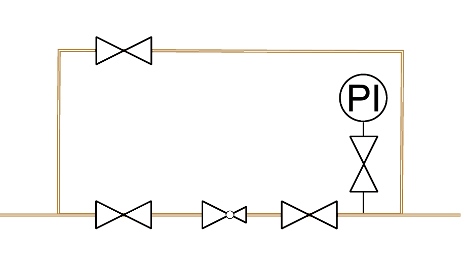
Oil pressure control module graphic
The oil pressure control module is used to maintain a constant oil pressure in the flow of the oil ring line. It consists of an oil pressure regulator, upstream and downstream shut-off valves that allow the oil pressure regulator to be removed, a pressure indicator (PI) and a bypass valve. The connection is always made downstream of the final branch line supplying the burner.
Oil circulating module, OCM
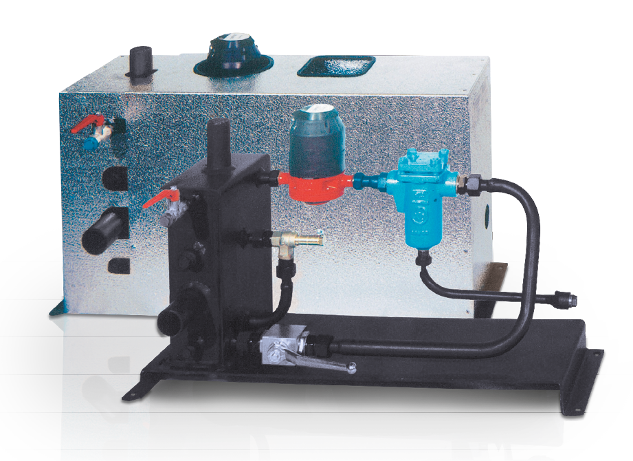
Oil circulation device (oil pan required)
| FI | Filter fitting |
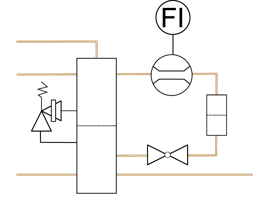
Oil circulation device graphic
The oil circulation device treats liquid fuels by filtering and separating air, and measures the oil flow rate. It is designed for light and heavy oil pressure atomising burners with a return nozzle system and is installed as a ready-to-connect unit, including cladding, for each burner in the oil supply system with a supply pressure of ≥ 1.5 bar. The oil circulation device is designed for use in a ring line system or a single-pipe system.
The module includes a dual-chamber oil reservoir for supplying oil directly to the burner and for collecting the return flow from the burner. The lines can be connected directly to the burner’s oil hoses.
It includes a filter valve (FI), the oil meter, shut-off valves, the pressure relief valve, a vent shut-off valve and drain plugs. When operating on heavy fuel oil, additional insulation is fitted beneath the sheet metal cladding.