
Flue systems
All components of a combustion system, starting with the burner and its associated fan, through to the boiler, flue gas heat exchanger, flue gas lines, silencer and chimney, must be carefully coordinated. Only then can flawless operation be guaranteed in all operating states and over the long term. A lack of coordination or incorrect execution of individual components leads to vibrations, noise, increased emissions or unstable combustion in the overall system.
The flue system begins at the end of the boiler and has the task of safely discharging the flue gases produced during combustion into the environment. This includes the flue gas lines inside and outside the boiler room, the chimney and any additional fixtures such as expansion fittings, silencers or flue gas flaps.
Flue systems must be designed in accordance with the national and local regulations as well as the applicable standards.

Reference to the BDH information sheet and TI 024
General requirements for flue systems in and on buildings are specified in DIN EN 1443. The design of the flue systems must comply with local building regulations and DIN V 18160.
For free-standing chimneys, the DIN 1056, DIN 4133 and DIN EN 13084-1 standards are applicable in addition to the building laws.
Specifications for fluid dynamics design can be found in standards DIN EN 13384 for flue systems in and on buildings and DIN EN 13084-1 for free-standing chimneys.
Flue gas ducts must be made of non-combustible construction materials and be resistant to the effects of flue gas and heat. The material of the entire flue system for hot water boilers must be suitable for temperatures up to 350 °C. If the boiler is equipped with a fourth pass or in the case of a heat recovery boiler for utilising waste heat from flue gases from a CHP unit or a gas turbine, the flue system must be suitable for the respective highest temperature.
Additional country-specific requirements are often imposed on the design of the flue system and the height of the chimney. Therefore, only the most important, functional planning principles are described here.
Flue gas line
The flue gas line connects the end of the boiler to the intake to the chimney. It should be routed as straight as possible, in a way that promotes good flow, and with as few bends as possible, in order to minimise pressure and thermal loss. Reductions or extensions should not be abrupt, but should always be carried out with a transition angle of no more than 30°. The flue gas line should also be connected to the chimney at an angle of 30° – 45°.
| Requirement | Implementation |
| Constant combustion chamber conditions | Designed for +0/-1 mbar at the end of the boiler or downstream of the flue gas/condensing heat exchangers One flue per boiler is recommended |
| Low pressure drop | Short, with few bends and designed for optimal flow |
| Low heat loss | Ensure adequate insulation |
| Draining condensate | Condensate drain connections and neutralisation |
| Ensure unobstructed access | Provide access and cleaning openings |
| Emissions measurement | Provide an emissions test port |
| Cleaning and inspection | Provide cleaning and inspection openings at all diversions |
| Compensating for thermal expansion | Expansion joints mandatory |
| Resistance | Temperature- (up to 350 °C), condensate-, corrosion-resistance |
| Compressive strength | Positive and negative pressure |
| Gas tightness | Gas tightness in accordance with EN 1856 |
| Risk of suffocation | Install flue gas and supply air dampers with safety-related limit switch |
General requirements for the flue gas lines
Dimensioning
The flue gas line, including all components such as flue gas flaps, expansion fittings and silencers, can usually be continued from the flue gas connection socket on the boiler to the chimney using the same nominal diameter.
When designing the system, the recommended speed should not exceed 16.5 m/s based on the boiler outlet temperature. As the guideline speed relates to the operating volume flow, the flue gas mass flow rate – which is usually specified – must be converted to the operating volume flow.
The ideal gas law can be used for the conversion.

Formula: Normal conditions and standard conditions
|
Example: Natural gas H: |
|
|
λ |
1.15 excess air |
|
|
10,000 flue gas mass flow [kg/h] |
|
|
1.244 flue gas standard density [kg/m³n] |
|
|
100 / 373.15 flue gas temperature [°C]/[K], after economiser |
|
= |
1.01325 ambient pressure [bar] (deviations from the standard conditions are disregarded) |

Particularly in the case of low chimney heights and long flue gas lines, the chimney manufacturer’s draught calculation may also require a larger nominal diameter.
Flue gas silencer
Flue gas silencers are designed to reduce the noise produced by the combustion process. To ensure effectiveness, the silencer must be designed to accommodate the frequencies emitted by the burner, the boiler capacity and the specified permissible noise emissions.
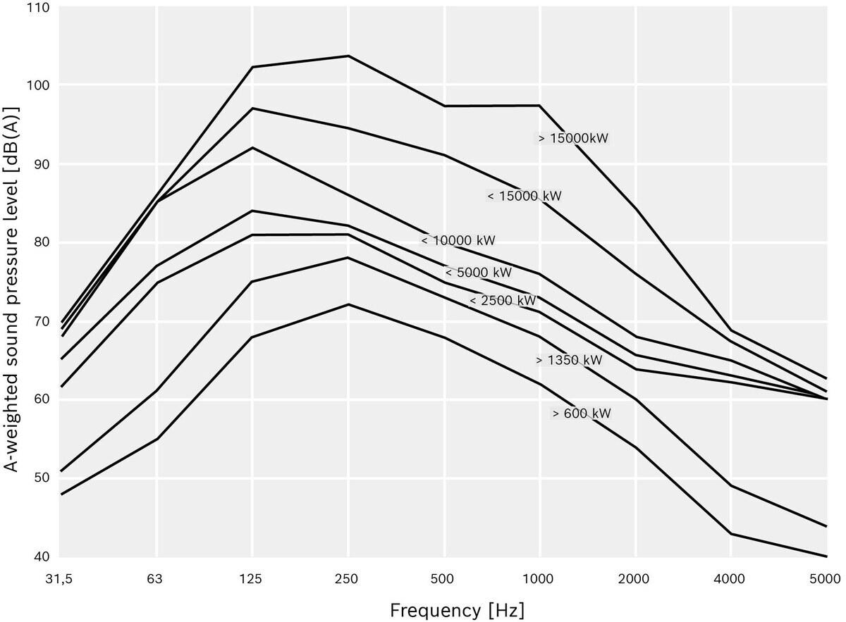
A-weighted frequency analysis and corresponding total sound pressure level as a function of the boiler heat output
| Boiler heat output | [kW] | ≤ 600 | ≤ 1.350 | ≤ 2.500 | ≤ 5.000 | ≤ 10.000 | ≤ 15.000 | > 15.000 |
| Expected value for the Total sound pressure level | [dB(A)] | 75 | 81 | 85 | 87 | 94 | 100 | 107 |
The values shown in the figure above (A-weighted frequency analysis and corresponding total sound pressure level as a function of the boiler heat output) are for guidance only and relate to a single boiler without a flue gas silencer. The measurement was taken at the chimney opening, 1 m away, at an angle of 45°.
The noise generated during combustion is transmitted as airborne sound via the surface of the flue system and is emitted at the top of the chimney. The noise produced by a boiler system consists mainly of low-frequency sounds.
This noise emission can be effectively reduced through the use of flue gas silencers. In order to comply with the prescribed sound emission values, the frequency spectrum of the exhaust sound at the chimney outlet of the boiler system must be taken into account when designing a flue gas silencer.
The diagram shown in the figure “A-weighted frequency analysis and corresponding total sound pressure level as a function of boiler heat output” illustrates the average sound pressure level of a boiler, measured at the chimney opening without a flue gas silencer in the flue system. Since the combustion system (e.g. due to the burner design or the flow pattern within the combustion chamber) and the flue system (e.g. due to the number of bends, length and diameter of the flue gas line) have a significant influence on the resulting values, only indicative values for the sound pressure level can be provided here. In the case of a multi-boiler system, a more complex calculation is required. In this case, the recommendation is to consult an expert.
When planning the flue gas line, it is important to bear in mind that, depending on the requirements, a considerable length of silencer may be necessary to reduce noise emissions; this must be installed either inside or outside the installation room before the flue gas enters the chimney.
Where there are strict requirements regarding noise emissions, e.g. in hospital settings, it is advisable to consult a noise assessment expert when specifying the design of a flue gas silencer, given the complexity of the issue.
The role of the chimney is to safely discharge flue gases and the pollutants they contain into the atmosphere, ensuring that they are carried away unimpeded by the natural air flow and that the pollutants are sufficiently diluted. It should be located in the immediate vicinity of the boiler house to avoid long flue gas ducts, and the flue gases should be discharged vertically upwards. Obstructions to the free flow of air caused by bends or rain covers are not permitted.
The minimum required height for the chimney is determined by national air quality standards.
In Germany, this is set out in the German Clean Air Regulations (TA-Luft). To this end, the quotient of the emission mass flow rate Q [kg/h] and the factor S, as specified in Appendix 6 of the TA-Luft, is calculated to determine the chimney height.
| Air pollutant factor Material | Factor S*) |
| Carbon monoxide CO | 7.5 |
| Sulphur oxides (sulphur dioxide SO2 and sulphur trioxide SO3), Specified as sulphur dioxide | 0.14 |
| Nitrogen oxides (NOx), specified as nitrogen dioxide | 0.1 |
*)Values for S in accordance with Appendix 6 of the German clean air regulations
For hot water boilers, nitrogen oxides are almost always the decisive factor when calculating chimney height.
In certain circumstances, an exemption from the requirement regarding chimney height may apply if Q/S does not exceed 10 kg/h. For lower Q/S ratios, the minimum chimney height of 10 m applies; for higher Q/S ratios, the chimney height is designed so that comparable values are achieved at the point of highest exposure, regardless of the emission mass flow rate. This must be checked individually.
|
Q |
Emission mass flow rate of the air pollutant emitted from the emission source [kg/h] |
|
S |
Factor for determining the chimney height |
Chimney cross-section and draught
The flue gases in the chimney have a higher temperature than the air outside. This creates an upward force in the chimney and the rising sections of the flue gas line, known as chimney draught. This helps to draw the flue gases out and creates a negative pressure in the chimney and parts of the flue gas line. The size of the flue is also linked to the temperature difference from the surrounding environment via the density.
The cross-sectional area of the flue must be large enough to ensure that the drag forces within the chimney from the end of the boiler onwards can be overcome by the lift forces. On the other hand, the cross-sectional area should not be too large, so that the flue gas speed at the chimney opening remains at least 6 m/s and does not create excessive negative pressure at the boiler end, particularly in the case of very tall chimneys.
The calculation of the flue gas line should always be undertaken by a contractor specialising in the installation of flue systems or by the boiler manufacturer.