
Circulation pumps
In hot water and heating boiler systems, heat is transferred through the circulation of water on both the generator and consumer sides. For this purpose, centrifugal pumps in various designs are used almost exclusively.
Minimum volume Qmin
The minimum volume Qmin is the minimum permissible discharge flow through the pump that is required to ensure adequate cooling of the mechanical seal.
The minimum volume depends on the medium temperature and is between 10 % and 30 % of the pump’s nominal volume flow.
Maximum permissible discharge flow Qmax
The maximum permissible discharge flow must not be exceeded in order to prevent cavitation in the pump. The maximum permissible discharge flow of the pump depends on the NPSH value.
NPSH value
The abbreviation NPSH stands for ""net positive suction head"" and is an important quantity for assessing the suction characteristics of a centrifugal pump. It enables conclusions to be drawn as to the pump’s resistance to the effects of cavitation during operation.
Cavitation is a mechanism that causes damage to the pump and must be avoided at all costs under all operating states in order to ensure a long service life.
As the fluid flows through the impeller of a centrifugal pump, the static pressure initially drops, particularly at the inlet to the blade channel, compared with the value upstream of the impeller. The extent of the pressure reduction depends on the speed, density and geometry of the impeller inlet, the viscosity of the fluid being pumped, as well as the operating point and speed profile of the inflow.
To prevent cavitation, the pressure upstream of the impeller must always be higher than the vapour pressure of the medium being pumped, regardless of the operating states.
The NPSH depends on the flow rate and the temperature. The higher the temperature, the lower the NPSH.
Important to know in practice:
The supply pressure at the pump’s intake connection must always be greater than NPSH value of the pump.
Wet-running pumps
So-called wet-running pumps are used for circulating heating water at flow rates of up to approximately 50 m3/h and discharge heads of up to approximately 10 m. The maximum medium temperature for this pump design is 110 °C.
The electric motor and the centrifugal pump form a single unit and are therefore sealed completely airtight from the surrounding environment, meaning that no mechanical seal is required to isolate the internal pressure of the pump from the atmosphere. This means that the pump is maintenance-free. The electric motor is cooled by the conveyed medium.
Structure of a wet-running pump
For flow rates, discharge heads or temperatures that exceed these limits, dry-running centrifugal pumps are used. These are more versatile in use and are generally more efficient.
Dry-running pumps
In a dry-running pump, the pump unit that comes into contact with the medium is structurally separated from the motor. The pump impeller is connected to the motor via a shaft and a coupling. The pump shaft is sealed in the part that comes into contact with the medium by means of a mechanical seal.
Depending on the required differential pressure (= discharge head) of the pump, there are single-stage and multi-stage centrifugal pumps.
For lower outputs, inline pumps are used, in which the suction and discharge connections are aligned in a straight line. These can be fitted directly into the piping. Block pumps are used for higher outputs. The discharge connection is offset by 90° from the intake connection. Block pumps must be levelled and secured on the foundation.
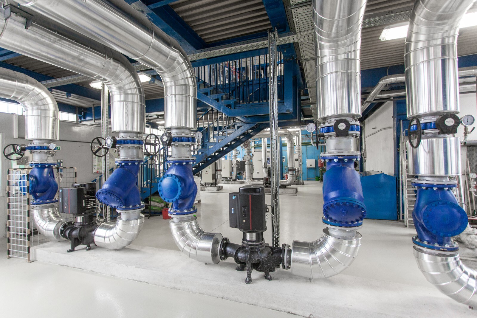
Inline pumps
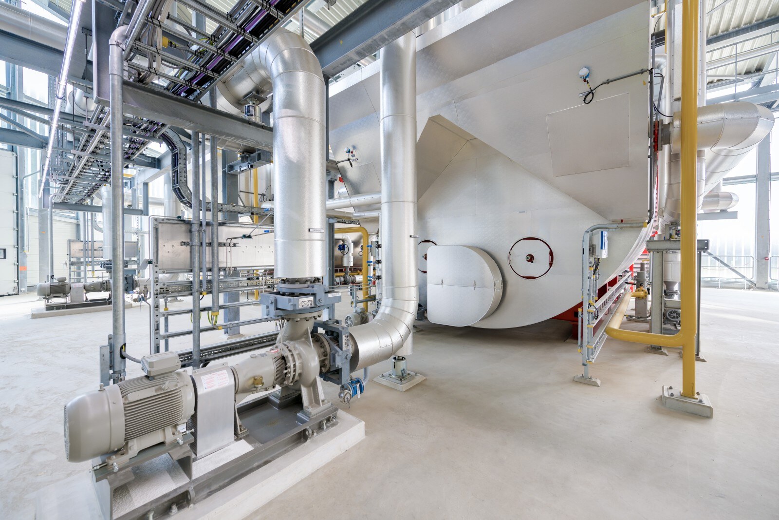
Block pump with axial inlet and radial outlet
Single-stage spiral pump with opposite intake and discharge connections in an inline configuration (intake and discharge connections are opposite each other and have the same diameter). The pump is fitted with a fan-cooled permanent-magnet synchronous motor. The motor efficiency should comply with the highest energy efficiency class, IE5. To regulate the speed, the motor is equipped with a frequency converter and a speed regulation system, both of which are housed in the motor’s terminal box. The electronic speed regulation allows the motor speed – and therefore the pump output – to be continuously adjusted to meet the current demand.
Vertical, multi-stage centrifugal pump with intake and discharge connections on opposite sides (inline design). The pump components that come into contact with the medium are made of cast iron (head and base) and stainless steel. Power is transmitted via a rigid, split coupling. The pump is fitted with a three-phase, fan-cooled permanent-magnet synchronous motor. The motor efficiency should comply with the highest energy efficiency class, IE5. To regulate the speed, the motor is equipped with a frequency converter – either integrated or mounted separately – and a speed regulation system, both of which are housed in the motor’s terminal box. The electronic speed regulation allows the motor speed – and therefore the pump output – to be continuously adjusted to meet the current demand.

Note regarding the maximum permissible medium temperature for dry-running centrifugal pumps:
In general, the permissible medium temperature for dry-running centrifugal pumps is determined by the permissible medium temperature at the mechanical seal and the materials used in the pump.
In standard designs, the mechanical seal in the pump head is directly exposed to the medium at the relevant operating temperature. Note that the maximum medium temperature is usually 140 °C.
In hot water pumps, a modified design connects the mechanical seal to the pumped medium via a cooling section, so that the temperature at the mechanical seal is, for example, only 120 °C, even though the pump is handling water at a temperature of, for example, 180 °C.
The most commonly used system for flow rate control in these pumps is the use of a frequency converter, which allows the pump speed to be varied or adjusted to meet the relevant demand.
In accordance with the hydraulic specifications and user requirements, the following control types are commonly used:- Constant or proportional differential pressure control, adjusted for volume flow, with differential pressure measurement across the pump
- Constant differential pressure control with differential pressure measurement at one or more weak points on the consumers
- Differential temperature control system
Characteristic curve of centrifugal pumps
Design data for the example:- Target volume flow Q = 25 m³/h
- Discharge head from the pressure loss calculation H = 12 m
- Medium temperature 60 °C
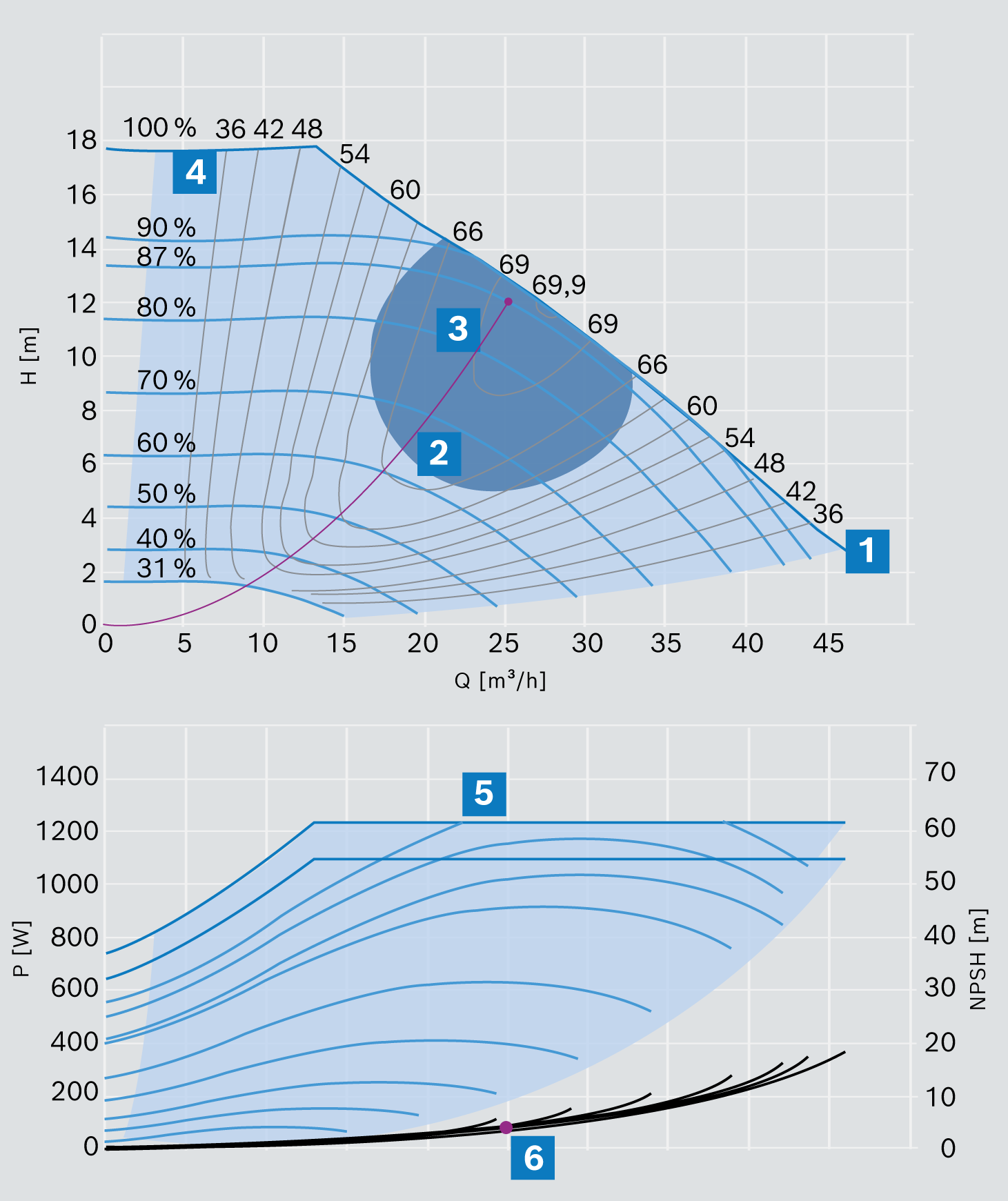
Typical pump curve of a single-stage controlled centrifugal pump with marked iso-efficiency curves (= lines of equal efficiency)
|
|
Pump curve at 100 % speed |
|
|
Installation curve |
|
|
Operating point in the design (the point where the system characteristic curve intersects with the pump characteristic curve) |
|
|
Curves of equal efficiency |
|
|
Pump electrical power consumption with motor [kW] |
|
|
NPSH value |


The system characteristic curve shown in red starts at the zero point in circulation systems and increases quadratically with the volume flow, as the pressure losses to be overcome in the piping and system also increase quadratically with the flow rate. The system’s operating point is always the point where the system characteristic curve intersects with the pump characteristic curve; in this example, this point is at 87 %. The design point of the pump system should be as close as possible to the point of optimum efficiency. This lies within the range between the first and second thirds of the maximum flow rate.
Important to know in practice:
For heating and hot water applications, the pump curves in manufacturers’ documentation always refer to water as the medium being pumped and a specific medium temperature.
- In selection programmes, the actual operating temperature can be entered and the density of the medium is calculated automatically
- The operating point is always the point of intersection between the system characteristic curve and the pump characteristic curve
- As pressure increases, the pump delivers a lower volume and the power consumption is reduced
- As pressure drops, the flow rate and electrical power consumption increase
- The NPSH value must be provided for each pump in order to prevent cavitation
Circulation mode in the hot water or heating system
In recirculation mode (e.g. in a heating system), the geodetic differences in elevation are eliminated due to the closed circuit. This simplifies the equation for the required discharge head as follows:
Hv then includes all pipe resistances and the resistances of all installed components, such as fittings, valves, boilers and heat exchangers, within the pump’s flow path on both the pressure and suction sides.
Hot water or heating system

The density of water decreases slightly as the temperature rises. At 10 baro between 943.5 [kg/m3] for 120 °C and 907.7 [kg/m3] for 160 °C. However, when designing hot water systems, it is generally safe to assume an average density of 926.5 [kg/m3].
Effect of the mounting height
To ensure adequate cooling of the pump motor, a reduction in pump performance must be expected at altitudes of 1,000 metres above sea level and above, due to the decreasing specific density of the cooling air.
In pumps with an integrated frequency converter, the motors are fitted with built-in overload protection, meaning that the motor speed is automatically reduced before an overload or overheating occurs. The pumps should therefore not be designed to operate at their power limit at an installation height of 1,000 m above sea level. It is helpful here to reach the required operating point at around 90 % of the pump speed.
Causes of pump damage
Cavitation
Cavitation refers to the formation and collapse of vapour bubbles in flowing liquids. The vapour bubbles form in places where the pressure falls below the vapour pressure corresponding to the temperature of the medium.In pumps, cavitation always occurs in the inlet area of the pump impeller, as this is where the pressure is lowest due to the combined suction-side resistances.
Falling below the minimum volume Qmin
If the minimum volume is not met, adequate cooling of the pump is not be guaranteed. As a result, the pump may overheat in places and the mechanical seals may start to leak.