
Condensing flue gas heat exchanger
Operating conditions
- Return temperature or heat sink (e.g., service water) < 60 °C required, preferably < 45 °C, as efficiency increases with lower temperatures
- The flue gas heat exchanger, as well as flue gas lines and the chimney, must be made of stainless steel
- For boilers up to approx. 3 MW, the flue gas heat exchanger has a full-flow design
- For boilers from approx. 3 MW, the flue gas heat exchanger has a partial-flow design
- Low-sulphur fuel is required
When utilising condensing technology, not only the sensible heat directly linked to the temperature is extracted from the flue gas, but also a portion of the condensation heat bound in the water vapour. This process creates liquid flue gas condensate, which must be drained from the flue gas path, neutralised, and discharged into the sewage system.
Corrosion-resistant materials in heat exchangers, moisture-resistant flue gas systems, and stainless steel chimneys make this possible without causing long-term corrosion damage. The decisive increase in efficiency is no longer due to the reduction of the flue gas temperature, but rather to the condensation rate of the water content in the flue gas, which is initially in vapour form. Under the right conditions, an additional efficiency improvement of up to 7% is possible. To achieve the highest possible condensation rate in a condensing flue gas heat exchanger, a sufficiently large and, above all, cool (temperature < 45 °C) water stream is required to serve as a low-temperature heat sink. The condensing flue gas heat exchanger should always be integrated at the coldest return point. Therefore, integration before the low loss header is advisable to efficiently utilise all operating states. In heating systems, this can be the coldest return flow, for example from a low-temperature heating circuit, which is then routed through the condensing flue gas heat exchanger in its own circuit. The condensing flue gas heat exchanger can be designed as an integrated version or installed downstream of the dry flue gas heat exchanger on the flue gas side, allowing it to be retrofitted.
As shown in the following diagrams, the downstream condensing flue gas heat exchanger is fed from the coldest return on the secondary side. This increases the overall system efficiency, thereby saving fuel and reducing CO2 emissions. In boiler systems with multi-fuel firing systems, where at least one fuel contains sulphurous components, the condensing flue gas heat exchanger must be a "stand-alone" version (not integrated into the boiler) with a bypass to prevent sulphurous condensate. A flue gas heat exchanger for condensing use can also be employed with low-sulphur fuel oil.
Heating/Hot water single boiler system with integrated condensing flue gas heat exchanger, with partial flow in the boiler circuit
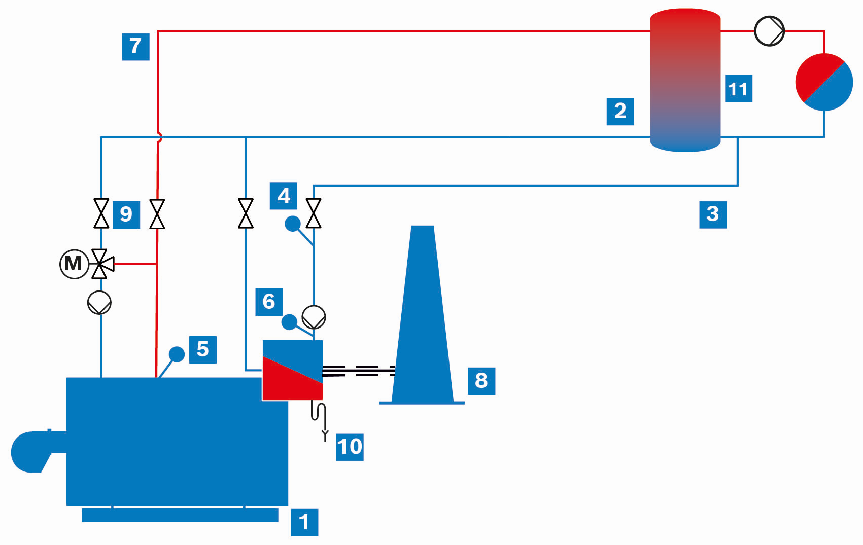
Hot water boiler system (UT-L and UT-M) with integrated condensing flue gas heat exchanger (simplified schematic diagram)
|
|
Hot water boiler |
|
|
Return |
|
|
Cold return < 50 °C |
|
|
Return temperature |
|
|
Flow temperature |
|
|
Eco intake temperature |
|
|
Flow |
|
|
Chimney |
|
|
Shut-off valve |
|
|
Condensate drain |
|
|
Low loss header |


Heating/Hot water single boiler system with integrated flue gas heat exchanger and stand-alone condensing flue gas heat exchanger with bypass, with partial flow in the boiler circuit
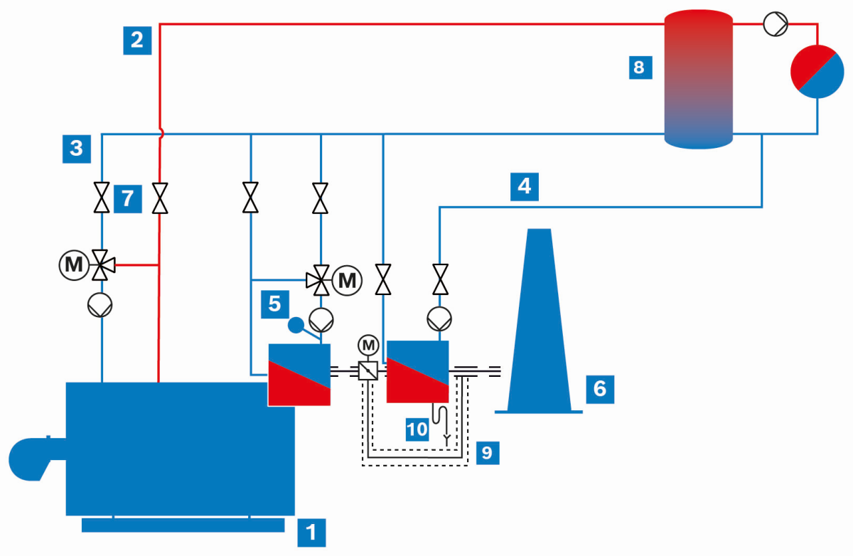
Hot water boiler system with condensing flue gas heat exchanger and bypass (simplified schematic diagram)
|
|
Hot water boiler |
|
|
Flow |
|
|
Network return |
|
|
Cold return < 50 °C |
|
|
Eco intake temperature |
|
|
Chimney |
|
|
Shut-off valve |
|
|
Low loss header |
|
|
Bypass |
|
|
Condensate drain |
Heating/Hot water single boiler system with integrated flue gas heat exchanger and stand-alone condensing flue gas heat exchanger, with partial flow in the boiler circuit
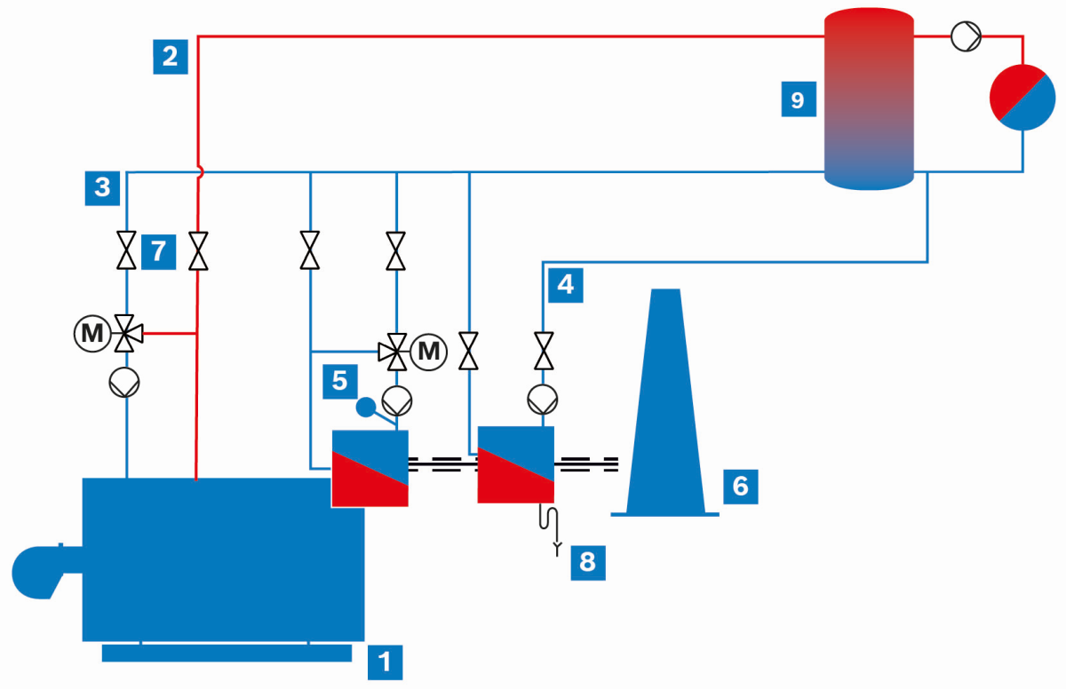
Schematic diagram of the integration of a separate condensing boiler flue gas heat exchanger into a hot water boiler system without bypass (simplified representation)
|
|
Hot water boiler |
|
|
Flow |
|
|
Return |
|
|
Cold return < 50 °C |
|
|
Eco intake temperature |
|
|
Chimney |
|
|
Shut-off valve |
|
|
Condensate drain |
|
|
Low loss header |
Heating/Hot water single boiler system with integrated flue gas heat exchanger and stand-alone condensing flue gas heat exchanger in the secondary circuit
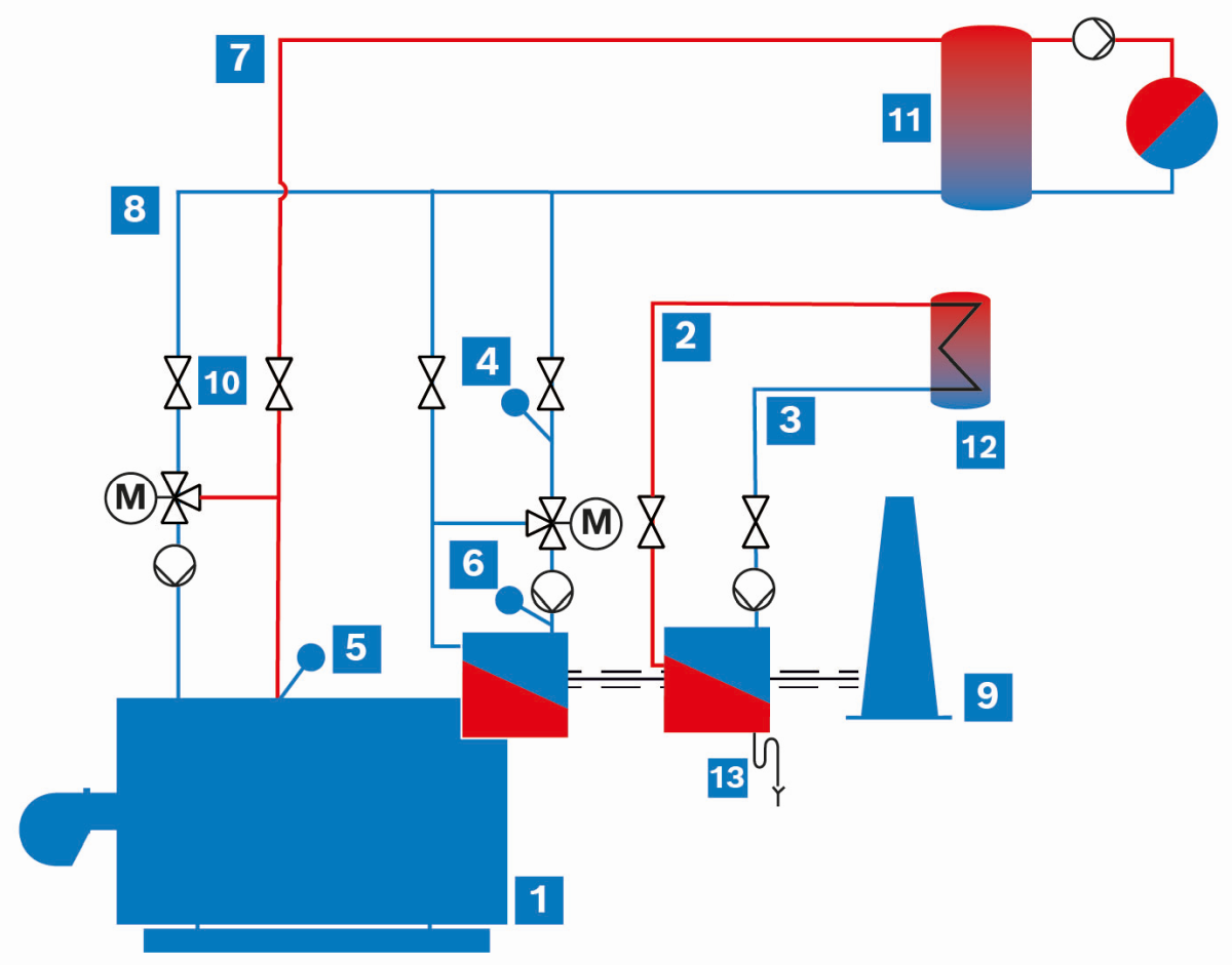
Hot water boiler system with exemplary use of potable water
|
|
Hot water boiler |
|
|
Potable water outlet |
|
|
Potable water inlet |
|
|
Return temperature |
|
|
Flow temperature |
|
|
Eco intake temperature |
|
|
Flow |
|
|
Return |
|
|
Chimney |
|
|
Shut-off valve |
|
|
Low loss header |
|
|
DHW cylinder |
|
|
Condensate drain |


Condensation can no longer occur at return temperatures above 60 °C.
Condensing flue gas heat exchangers can also be used to heat potable water. This variant is particularly interesting if, in addition to hot water, a larger amount of domestic hot water is also required. Since the cold water temperature is usually between 5 and 10 °C throughout the year, this provides an ideal temperature sink for condensing the water contained in the flue gas. The low temperatures mean that the highest condensation rates and therefore the best overall efficiency can be achieved. It makes sense to integrate the potable water into a cylinder. It should also be noted that this usually only allows the potable water to be preheated to approx. 45 °C. For the frequently required DHW temperatures of 60 °C, reheating must be carried out.
Depending on the temperature level that can be provided in the systems and with the optimal design of the condensation flue gas heat exchanger, the flue gas temperature can be reduced and, above all, the condensation rate, which is decisive for the increase in efficiency, can be significantly increased. With the condensing technology, this results in efficiency levels of over 100 %, since the efficiency is based on the lower net calorific value.
Information about the net calorific value, gross calorific value
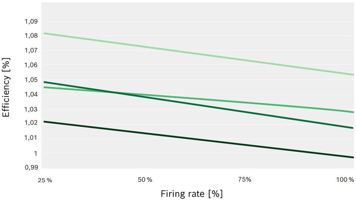
Efficiency with condensing flue gas heat exchanger
|
|
ƞ with Eco and condensing Eco 35 °C |
|
|
ƞ with Eco and condensing Eco for potable water 10 °C |
|
|
ƞ with Eco and condensing Eco 35 °C, expanded heating surface |
|
|
ƞ with Eco and condensing Eco for potable water 10 °C, expanded heating surface |


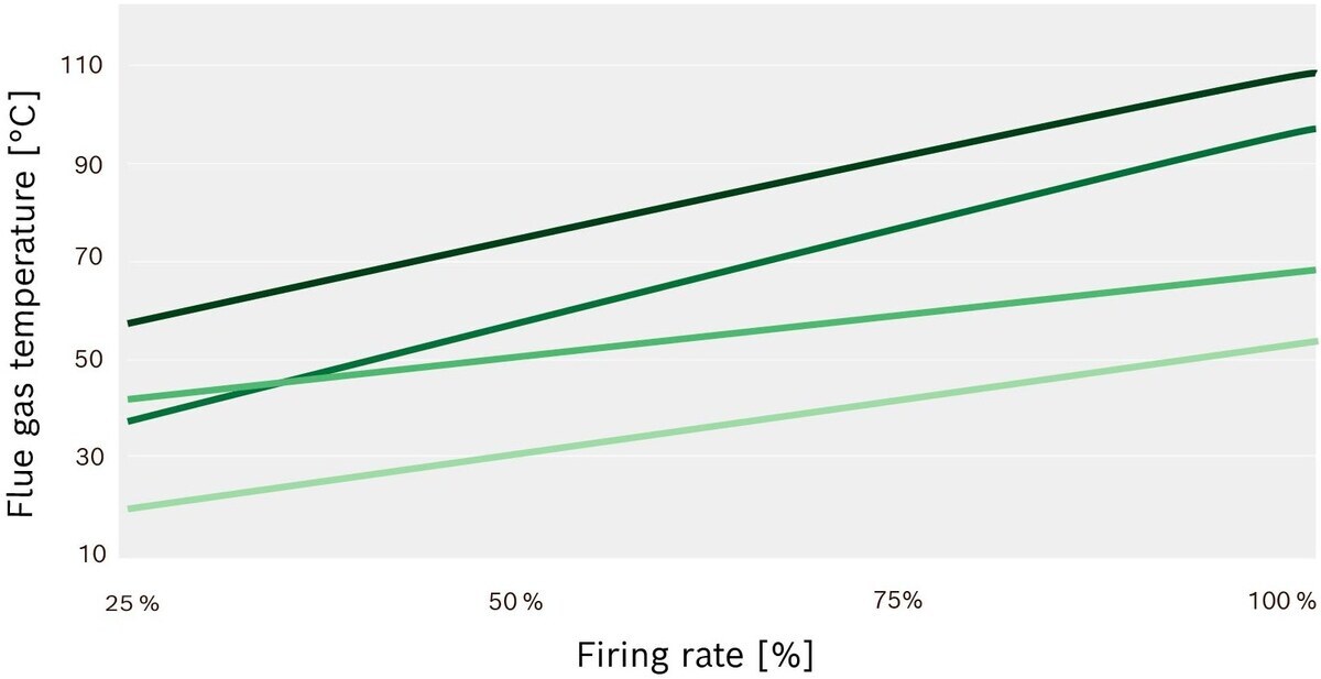
Flue gas temperature with condensing flue gas heat exchanger
|
|
TFluegas with Eco and condensing Eco 35 °C |
|
|
TFluegas with Eco and condensing Eco for potable water 10 °C |
|
|
TFluegas with Eco and condensing Eco 35 °C, expanded heating surface |
|
|
TFluegas with Eco and condensing Eco for potable water 10 °C, expanded heating surface |
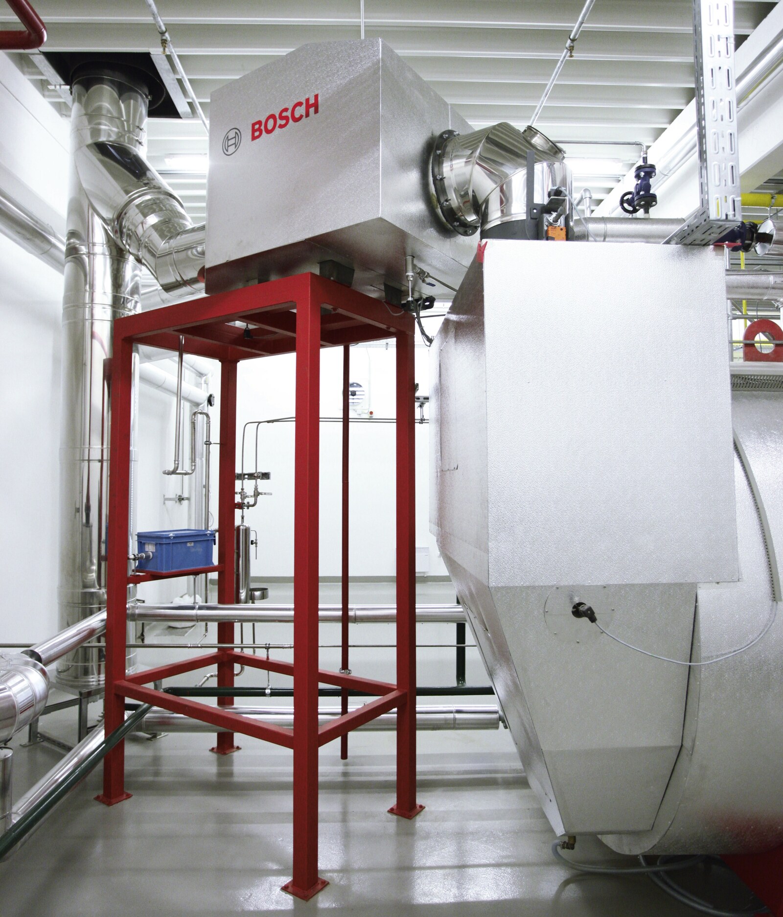
Condensing flue gas heat exchanger downstream
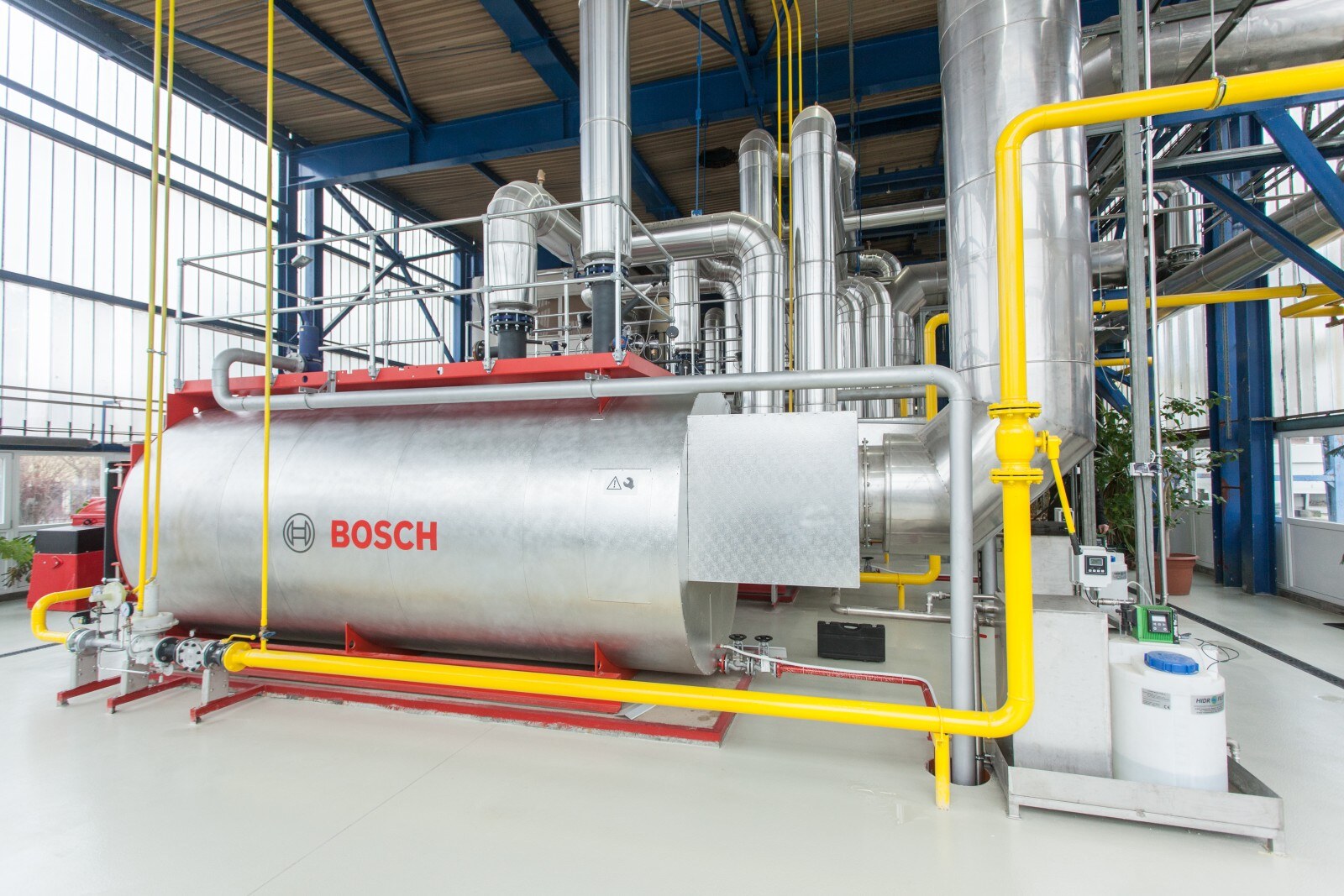
Integrated condensing flue gas heat exchanger, full flow