
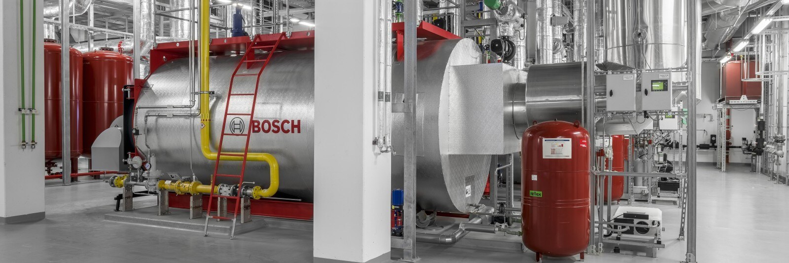
Pressure-maintaining systems
When water is heated, its volume increases. Since water can be regarded as incompressible within the relevant temperature range, even a small rise in temperature would lead to a very sharp increase in pressure if its expansion were restricted within a closed system.

Example: Content 30 m³; temperature increase from 40 to 50 °C
Theoretical increase in volume of 126 litres
The pressure-maintaining system is designed to accommodate the expansion volume caused by a rise in temperature, thereby keeping the pressure in the system virtually constant. As the heating water cools and its volume decreases, water must be topped up in the heating and hot water system in order to compensate for the drop in pressure in the heating water. This ensures that the pressure in the system is maintained and prevents the heating water from evaporating, the build-up of negative pressure and the occurrence of cavitation.
The pressure-maintaining system ensures that the maximum pressure in the system is not exceeded and that the pressure in the system does not fall below the minimum. In all heating and hot water systems, maintaining the correct pressure is essential for the safe and reliable operation of the entire system. Pressure maintenance is a mandatory safety-critical component in heat generation systems.
Information about safety pressure
In addition, the pressure-maintaining system can store heating water as a reserve in order to compensate for losses caused by normal leaks. Pressure-maintaining systems can generally be divided into two groups:
Static pressure maintenance
The static pressure maintenance is achieved using one or more diaphragm expansion vessels (MAG). The role of the MAG is to accommodate the expansion volume of the water circuit as its temperature rises. This ensures that the system operates within the permissible pressure limits. It is a steel tank divided into a gas chamber and a water chamber. The separation is achieved by means of a flexible diaphragm. Static pressure maintenance requires no auxiliary power, as the process relies solely on the compression or expansion of the nitrogen in the vessel’s gas chamber. Such pressure-maintaining systems are typically used for rated heat outputs of up to 1,000 kW. The correct design and presetting of the gas cushion are essential for the system to function optimally. Regular maintenance of the vessel, including a check of the supply pressure, must be carried out.

Schematic diagram of the diaphragm expansion vessel
|
|
Gas filling valve |
|
|
Gas chamber |
|
|
Full-diaphragm |
|
|
Water chamber |
|
|
Water-side connection |
|
|
Shut-off valve |


Connection point for pressure maintenance – diaphragm expansion vessel (MAG)
Firstly, the standard states that the MAG should preferably be installed in the return of the heating or hot water system, so as not to expose the diaphragm to unnecessarily high temperatures.
The way in which the pressure-maintaining system is hydraulically integrated into the system has a fundamental influence on the variation in working pressure. This is made up of the static pressure level of the pressure-maintaining system and the differential pressure generated when the circulation pump is in operation. Two variants are listed below:
Follow-up pressure maintenance
The pressure maintenance is integrated on the pressure side, i.e. downstream of the circulation pump. When determining the static pressure, the system-specific differential pressure contribution of the circulation pump (50 – 100 %) must be taken into account.
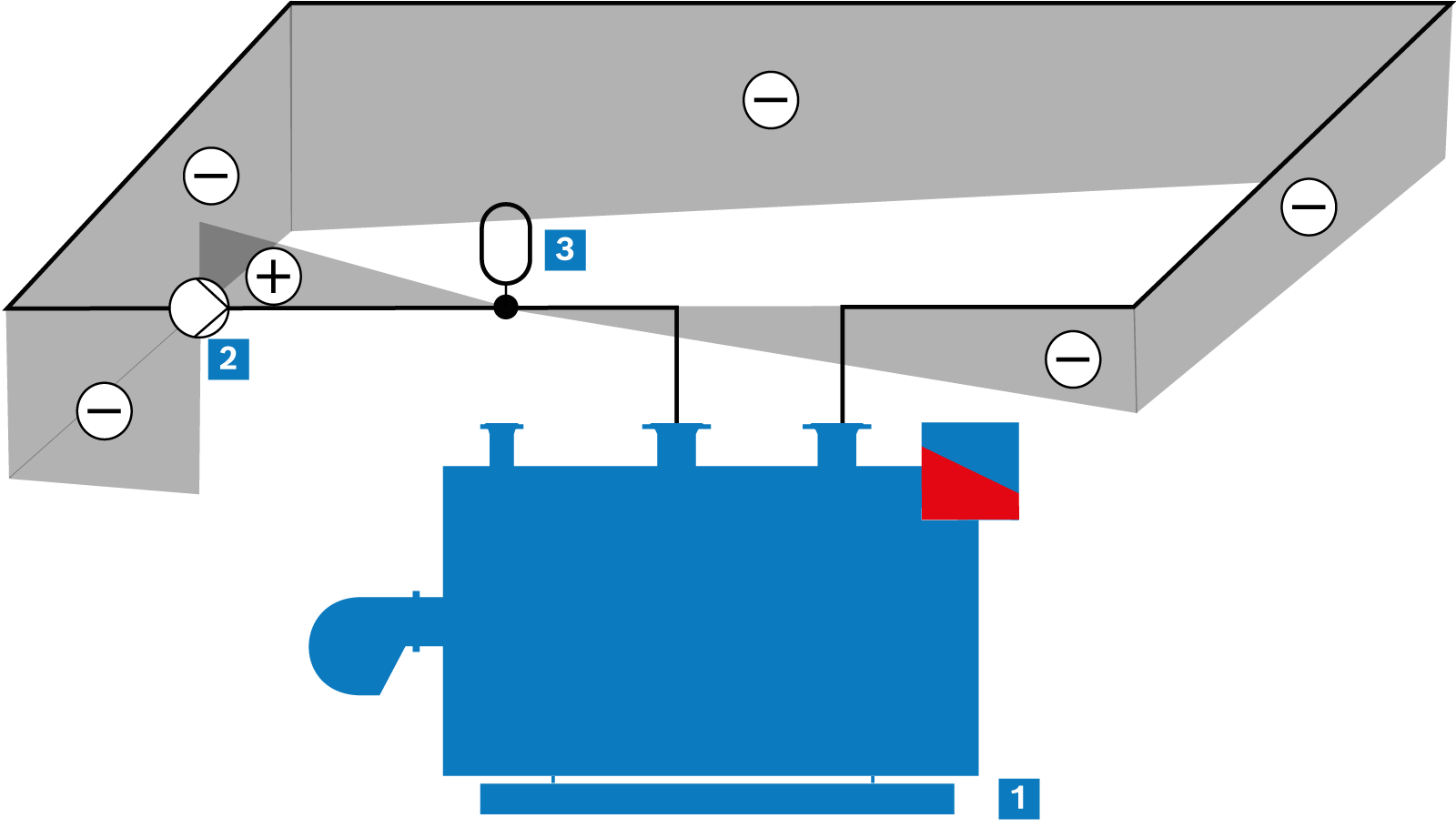
Follow-up pressure maintenance
|
|
Heat generator |
|
|
Pump |
|
|
MAG |
Supply pressure maintenance (suction pressure maintenance)
The pressure maintenance is integrated on the suction side, i.e. upstream of the boiler circuit pump.
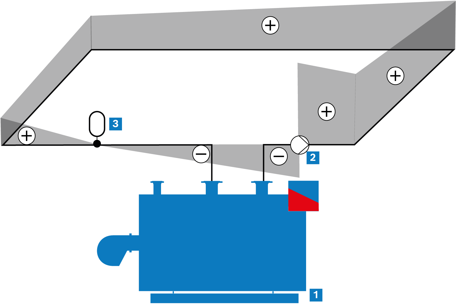
Supply pressure maintenance
|
|
Heat generator |
|
|
Pump |
|
|
MAG |
The choice between downstream and upstream maintenance depends on the specific requirements of the hot water system. Pressure maintenance is a simple and cost-effective solution for demanding systems.
The supply pressure maintenance offers more precise pressure regulation and is used in larger systems where stability is a key requirement.
Dynamic pressure maintenance
Two systems are typically used for dynamic pressure maintenance:
- Pump-controlled pressure maintenance
- Compressor-controlled pressure maintenance
Both systems rely on auxiliary power and can respond individually to changes in pressure caused by increases or decreases in volume. The system pressure can be maintained within tighter limits than is possible with static pressure maintenance.
The diagram “Pump pressure maintenance structure” shows the structure of the pump pressure-maintaining system, while the diagram “Compressor-controlled pressure-maintaining system” shows that of the compressor-controlled pressure-maintaining system. As with the MAG, a steel vessel fitted with a diaphragm is divided into two sections. However, when the pump is maintaining pressure, the gas chamber is connected to the outside air. If the pressure in the system rises, heating water is fed into the vessel via the overflow valve. In the process, the air in the gas chamber is displaced from the vessel. If the pressure in the system then drops, a pump returns heating water from the vessel to the system and air flows into the gas chamber.
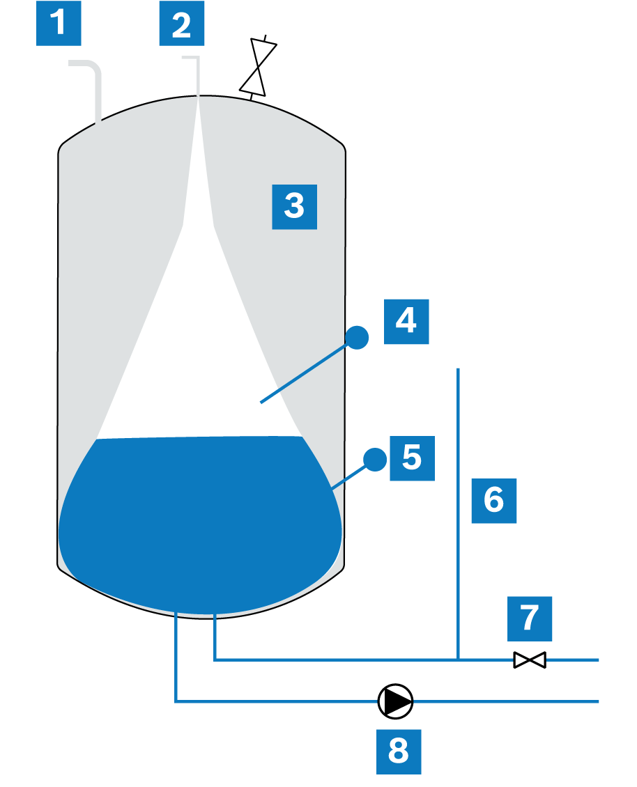
Pump pressure maintenance structure
|
|
Opening to the outside |
|
|
Air vent |
|
|
Gas chamber |
|
|
Diaphragm |
|
|
Water chamber |
|
|
Replenishment |
|
|
Overflow valve |
|
|
Pump |


In compressor-controlled pressure maintenance, air is released from the gas chamber via an overflow valve as soon as the pressure in the system rises. This allows the water to expand and flow into the container. The pressure in the gas chamber can then be increased using a compressor. This causes the heating water to be forced from the vessel into the heating system as soon as the pressure in the heating system drops.
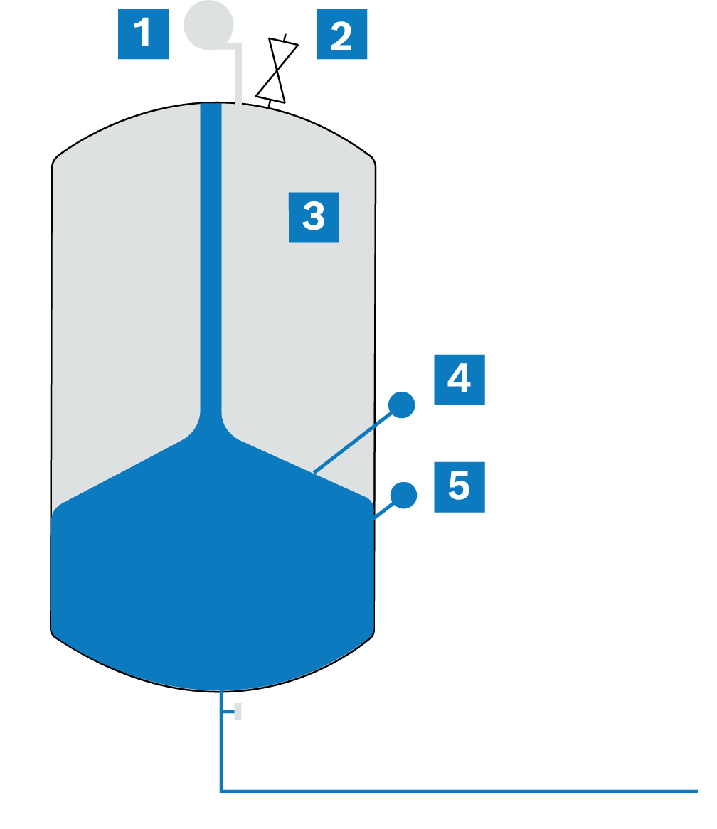
Structure of the compressor-controlled pressure maintenance
|
|
Compressor |
|
|
Overflow valve |
|
|
Gas chamber |
|
|
Diaphragm |
|
|
Water chamber |