
Pipework
When installing pipework systems, the terms nominal diameter (DN) and nominal pressure (PN) of a pipe are used as identifying characteristics to define compatible components, such as flange connections. The nominal diameter and nominal pressure are each standardised according to the geometric step size.
The dimensioning of piping – that is, determining the nominal diameter and nominal pressure for pipes and valves/fittings – always involves striking a balance between the technical requirements, such as keeping pressure loss or thermal loss to a minimum, and the associated investment and running costs. For each pipeline and each system, this results in a different optimal balance between investment and running costs. Because the curve is generally flat in the area where total costs are at their lowest, two nominal diameters often fall within the optimal range.
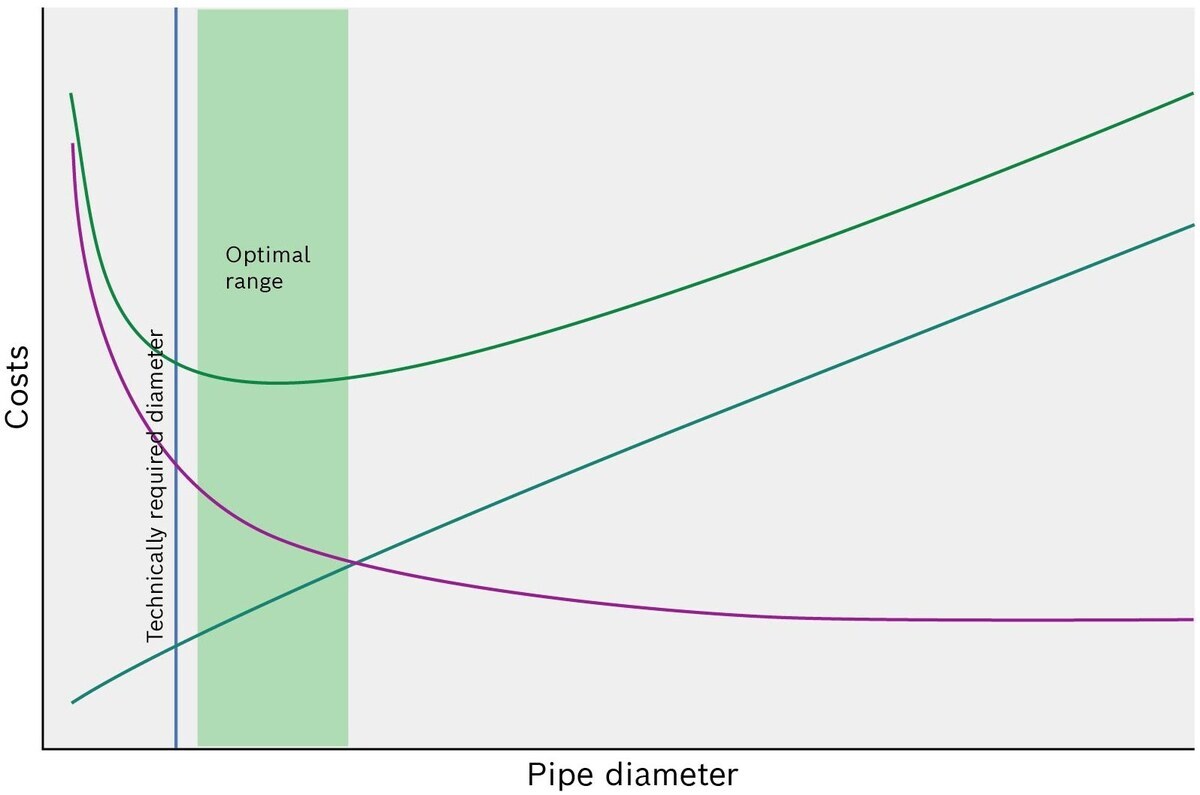
An illustrative, schematic breakdown of costs for pipe sizing
|
|
Total costs |
|
|
Running costs |
|
|
Investment costs |


The following steps should be followed when designing pipework:
- Specify the nominal diameter
- Specify the nominal pressure
- Select the material
- Specify the span lengths
- Note the heat expansion
- Take note of the specific characteristics of the medium during installation
- Specify the insulation
However, as a detailed analysis would require consideration of numerous system-specific, technical and commercial parameters, pipelines are usually designed using empirically derived values that are both economically viable and technically necessary as guidelines for flow velocity. Depending on the medium and the application, these guidelines have proven to be effective in practice in many systems. The following table can be used for dimensioning in the boiler house.
| Medium | Application range | Recommended speed |
| Water | Flow and return lines in the boiler house | 2 (1.5–3) m/s |
| Flue gas | 16.5 m/s | |
| Oil | Light fuel oil, suction side Light fuel oil, pressure side Heavy fuel oil, suction side Heavy fuel oil, pressure side |
0.5 m/s 1 m/s 0.3 m/s 0.5 m/s |
| Natural gas | No specifications (design based on pressure loss) |
Typical design flow rates (guide speeds) for pipe dimensioning

Flow and return pipes in the boiler house: 2 (1.5–3) m/s
Flow and return pipes in local and district heating networks are not usually dimensioned according to the guide speed, but according to guidelines for pressure loss per 100 m. Typical pressure loss values range from 100 to 300 Pa per 100 m.
Determining the nominal diameter DN
The nominal diameters in the table below are given without units. They are only approximately equal to the internal diameter of the pipe in mm. This is due to the manufacturing process, as the tools used to produce the pipes are determined by the external diameter, meaning that the internal diameter varies depending on the wall thickness. For rough dimensioning, it is usually sufficient to use the nominal diameter as the basis for calculating the internal diameter.
|
Nominal diameter |
External diameter d1 |
Nominal diameter |
External diameter d1 |
Nominal diameter |
External diameter d1 |
||||
|
6 |
10.2 |
80 |
88.9 |
500 |
508.0 |
||||
|
8 |
13.5 |
100 |
114.3 |
600 |
610.0 |
||||
|
10 |
17.2 |
125 |
139.7 |
700 |
711.0 |
||||
|
15 |
21.3 |
150 |
168.3 |
800 |
813.0 |
||||
|
20 |
26.9 |
200 |
219.1 |
900 |
914.0 |
||||
|
25 |
33.7 |
250 |
273.0 |
1,000 |
1,016.0 |
||||
|
32 |
42.4 |
300 |
323.9 |
1,200 |
1,219.0 |
||||
|
40 |
48.3 |
350 |
355.6 |
1,400 |
1,422.0 |
||||
|
50 |
60.3 |
400 |
406.4 |
1,600 |
1,626.0 |
||||
|
65 |
76.1 |
450 |
457.0 |
Pipe diameter (EN 10255:2004+A1:2007, EN 1092-1:2013-04, Table A.1)
The required nominal diameter can then be calculated as follows:


In order to optimise the nominal diameter calculated on the basis of an approved guide speed, it may in some cases – for example, in the case of particularly long pipework – be advisable to use specialist design software to recalculate and optimise the nominal diameter of the pipework.
Determining the nominal pressure PN
The nominal pressure is a standardised pressure stage for pipes and valves/fittings . It serves as an indicator of a component’s mechanical and dimensional properties. Components with the same nominal diameter and the same nominal pressure are compatible with one another. The nominal pressure corresponds to the maximum permissible overpressure [bar] at a reference temperature of 20 °C.
However, the maximum permissible overpressure for a component depends not only on the material but, above all, on the temperature. At higher temperatures, the maximum permissible working pressure falls below the nominal pressure. Pipes or valves/fittings must not be operated at nominal pressure.
The pressure-temperature assignment of flanges is determined according to the material groups. The following materials and material groups are commonly used in steam boiler applications:
|
Material group |
Material type |
Material number |
Material |
|
3E0 |
Unalloyed steels with guaranteed strength properties at elevated temperatures |
1.0352 |
P245GH |
|
3E1 |
Unalloyed steels with specified properties at ≤ 400 °C, upper yield point > 265 N/mm² |
1.0460 |
P250GH |
|
4E0 |
Low-alloy steels containing 0.3 % molybdenum |
1.0426 |
P280GH |
|
12E0 |
Standard carbon content, stabilised with Ti or Nb |
1.4541 |
X6CrNiTi18-10 |
|
15E0 |
Standard carbon content, alloyed with molybdenum, stabilised with Ti or Nb |
1.4571 |
X6CrNiMoTi17-12-2 |
Material groups according to EN 1092-1:2013-04, Table 9, G.2.2, G.3.2, Table D.1
The diagram below shows the pressure-temperature curves for different nominal pressure stages. Refer to the information in the “Tools – pressure-temperature mapping” section, which contains the tables for the diagram.
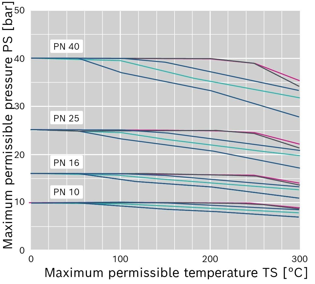
Pressure-temperature assignment for flanges in accordance with EN 1092-1
|
|
3E0 |
|
|
3E1 |
|
|
4E0 |
|
|
12E0 |
|
|
15E0 |


Determining the material
The following table sets out only the minimum requirements for material selection. In the event of special installation conditions, customer requirements or national or local regulations, alternative materials may also be used.
Copper-containing pipe materials must be avoided in all pipes leading to and from the steam boiler, as well as in the condensate and make-up water systems.
|
Range of applications |
Piping material |
|
Flow and return lines |
Steel with an Inspection Certificate |
|
Safety valve blowoff lines |
Steel |
|
Venting and drainage lines |
Steel |
|
Seat drainage (safety valves) |
Copper or stainless steel |
|
Softened water |
Plastic (cold) or stainless steel (after heating) |
Minimum requirements for material selection
Determining the span lengths
A sufficient number of correctly designed supports must be provided to ensure that pipework does not deform excessively under the influence of weight (dead weight, contents, valves/fittings and insulation) and other forces (e.g. at diversions).
The requirements for pipe supports are set out in EN 13480-3.
Pipes and flanges for water and steam
|
|
|
PN 40 |
Max. span |
|
10 |
17.2 |
2.0 |
– |
|
15 |
21.3 |
2.0 |
– |
|
20 |
26.9 |
2.3 |
– |
|
25 |
33.7 |
2.6 |
2.9 |
|
32 |
42.4 |
2.6 |
3.2 |
|
40 |
48.3 |
2.6 |
3.5 |
|
50 |
60.3 |
2.9 |
3.9 |
|
65 |
76.1 |
2.9 |
4.7 |
|
80 |
88.9 |
3.2 |
5.4 |
|
100 |
114.3 |
3.6 |
6.2 |
|
125 |
139.7 |
4.0 |
6.9 |
|
150 |
168.3 |
4.5 |
7.5 |
|
200 |
219.1 |
6.3 |
8.6 |
|
250 |
273 |
7.1 |
9.7 |
|
300 |
323.9 |
8.0 |
10.6 |
|
350 |
355.6 |
8.8 |
11.1 |
|
400 |
406.4 |
11.0 |
11.8 |
|
500 |
508 |
14.2 |
12.5 |
|
600 |
610 |
16.0 |
13.2 |
Span widths of piping (distance between supports)
1) Requirements for the span L1:- In accordance with EN 13480-3:2014 – filled with water, insulation thickness 80 mm
- With interpolated data added
- L1 deflection limit: up to DN 50 = 3 mm deflection; from DN 65 = 5 mm deflection
- For further details, see EN 13480-3
Thermal expansion
When solids are heated, they expand; when they cool down, they contract again.
This effect must be taken into account at many points within a steam boiler system, particularly in areas where high temperatures may occur during operation.
The following points are worth noting with regard to planning and installation:
- Planning and installation of suitable pipe fixings (brackets, sliding points, reference points) in the correct locations
- Compensating for the expansion in pipework by:
- Expansion joint (L- or Z-shaped joint)
- U-elbow
- Lyra-shaped expansion loop (Omega elbow)
- Axial or lateral compensators
- Compensation for expansion in boilers and containers by
- Sleeve bearings at feet and base frame
Expansion fittings and expansion joints on supply and discharge pipes The following equation can be used to calculate linear thermal expansion:

|
Coefficients of expansion for different steels Low-alloy steel (ferritic): Stainless steels (austenitic): |
The required expansion joint lengths to accommodate thermal expansion must be determined in accordance with generally accepted engineering practice. The AD 2000 technical note HP 100 R can be consulted to calculate the required expansion joint lengths.
Minimum clearance from the structure and adjacent pipework
When installing pipework and insulation, and for maintenance purposes, a gap of at least 50 - 100 mm should be maintained. DIN 4140, the technical standard commonly used for insulation work, recommends a minimum distance of 100 mm.
To minimise the spacing, flange connections on pipe bridges should be arranged in a staggered pattern.
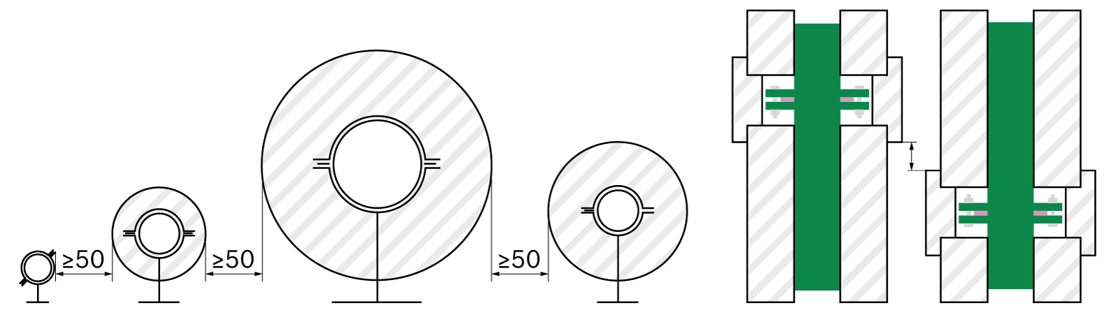
Flow and return lines (main lines)
Apart from thermal expansion, there are often no special considerations to bear in mind for flow and return pipes. In some cases, a flow speed of ≤ 2.3 m/s may be acceptable for short lines.
Discharge pipe in the liquid area
When installing the safety valve discharge pipe for liquids, the following criteria must be observed:
- The discharge pipe of a safety valve connected to a water chamber must be fitted with a pressure-relief and water-separator tank.
- The system on the discharge side of the safety valve must be designed in such a way that, during venting, the internal back pressure does not exceed 10 % of the excess pressure.
- The pipe section between the safety valve outlet and the pressure relief and water separator tank must be routed with a gradient (≥ 0.5 %).
- If there is an existing drainage hole at the seat of the safety valve, additional drainage should be provided.
- The drainage line must be routed at a gradient without any constrictions.
- The drainage system must not be blocked by dirt or foreign objects.
- The condensate collected in the pressure-relief and water-separator tank must be safely drained and cooled.
- The pipe section between the safety valve outlet and the pressure relief and water separator tank must be routed and secured in such a way that thrust, bending and torsional forces are prevented from acting on the safety valve (e.g. by means of supports or spring hangers). The reaction forces during blow-out must be taken into account.
- During blow-out, high temperatures, high flow speeds and flow noises occur. The discharge pipe on the pressure relief and water separator tank must therefore discharge into the open air in such a way that it does not pose any risk.
- The discharge pipe on the pressure relief and water separator tank must be kept separate from other pipes (e.g. vent, expansion and safety valve discharge pipes) and protected against freezing.
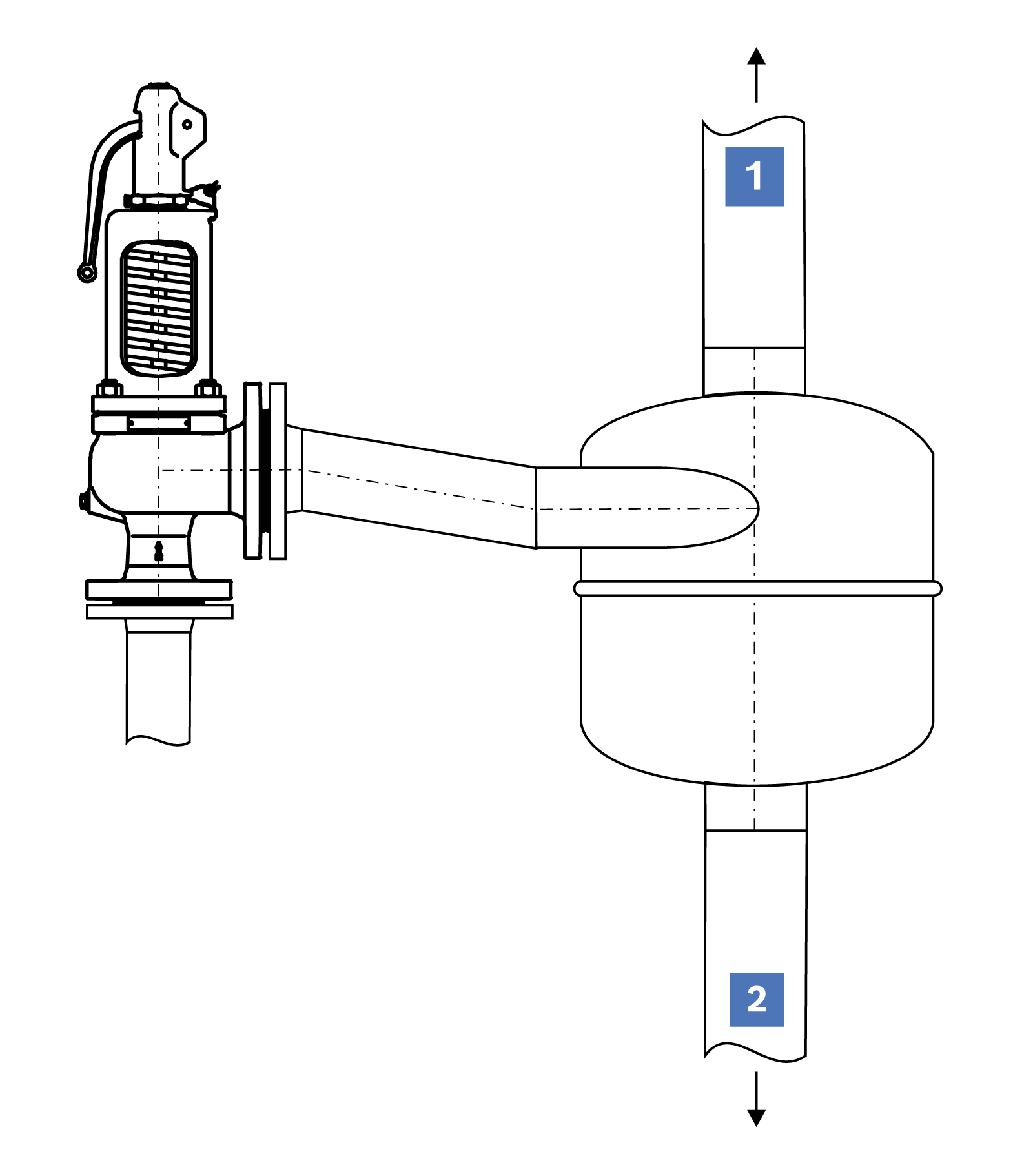
Safety valve with pressure relief and water separator tank
|
|
Discharge pipe routed safely over the roof |
|
|
Drain the drainage line safely and allow it to cool down |


Flue gas system
The flue system begins at the end of the boiler and has the task of safely discharging the flue gases produced during combustion into the environment. This includes the flue gas lines inside and outside the boiler room, the chimney and any additional fixtures such as expansion fittings, silencers or flue gas flaps.
All components of a combustion system, starting with the burner and its associated fan, through to the boiler, economiser, flue gas lines, silencer and chimney, must be carefully coordinated. Only then can flawless operation be guaranteed in all operating states and over the long term. A lack of coordination or incorrect execution of individual components leads to vibrations, noise, increased emissions or unstable combustion in the overall system.
Flue systems must be designed in accordance with the national and local regulations as well as the applicable standards.
General requirements for flue systems in and on buildings are specified in DIN EN 1443. The design of the flue systems must comply with local building regulations and DIN V 18160.
For free-standing chimneys, the DIN 1056, DIN 4133 and DIN EN 13084-1 standards are applicable in addition to the building laws.
Specifications for fluid dynamics design can be found in standards DIN EN 13384 for flue systems in and on buildings and DIN EN 13084-1 for free-standing chimneys.
Flue gas ducts must be made of non-combustible construction materials and be resistant to the effects of flue gas and heat. The material of the entire flue system for steam boilers must be suitable for temperatures up to 350 °C. If the boiler is equipped with a fourth pass or in the case of a heat recovery boiler for utilising waste heat from flue gases from a CHP unit or a gas turbine, the flue system must be suitable for the respective highest temperature.
Additional country-specific requirements are often imposed on the design of the flue system and the height of the chimney. Therefore, only the most important, functional planning principles are described here.
Flue gas line
The flue gas line connects the end of the boiler to the intake to the chimney. It should be routed as straight as possible, in a way that promotes good flow, and with as few bends as possible, in order to minimise pressure and thermal loss. Reductions or extensions should not be abrupt, but should always be carried out with a transition angle of no more than 30°. The flue gas line should also be connected to the chimney at an angle of 30° – 45°.
Requirement |
Design |
Constant conditions in the combustion chamber |
Rated at +0/-1 mbar at the boiler outlet |
Less pressure drop |
In short, few bends and aerodynamic |
Low thermal loss |
Ensure proper insulation |
Drain condensate |
Condensate drain connections and neutralisation |
Ensure unobstructed access |
Provide access and cleaning openings |
Emissions measurement |
Provide an emission test port |
Cleaning and inspection |
Provide cleaning and inspection openings at all diversions |
Compensate for thermal expansion |
Provide for expansion fittings |
Resistance |
Temperature- (up to 350 °C), condensate-, corrosion-resistance |
Compressive strength |
Positive and negative pressure |
Gas tightness |
Gas tightness in accordance with EN 1856 |
Risk caused by air shortage |
Integrate flue gas and supply air dampers with safety-related limit switch |
General requirements for the flue gas lines
Dimensioning
The flue gas line, including all components such as flue gas flaps, expansion fittings and silencers, can usually be continued from the flue gas connection socket on the boiler to the chimney using the same nominal diameter.
When designing the system, the recommended speed should not exceed 16.5 m/s based on the boiler outlet temperature. As the guideline speed relates to the operating volume flow, the flue gas mass flow rate – which is usually specified – must be converted to the operating volume flow.
The ideal gas law can be used for the conversion.

Formula: Normal conditions and standard conditions
|
Example: Natural gas H: |
|
|
λ |
1.15 excess air |
|
|
10,000 flue gas mass flow [kg/h] |
|
|
1.244 flue gas standard density [kg/m³n] |
|
|
100 / 373.15 flue gas temperature [°C]/[K], after economiser |
|
= |
1.01325 ambient pressure [bar] (deviations from the standard conditions are disregarded) |

Particularly in the case of low chimney heights and long flue gas lines, the chimney manufacturer’s draught calculation may also require a larger nominal diameter.
Flue gas silencer
Flue gas silencers are designed to reduce the noise produced by the combustion process. To ensure effectiveness, the silencer must be designed to accommodate the frequencies emitted by the burner, the boiler capacity and the specified permissible noise emissions.
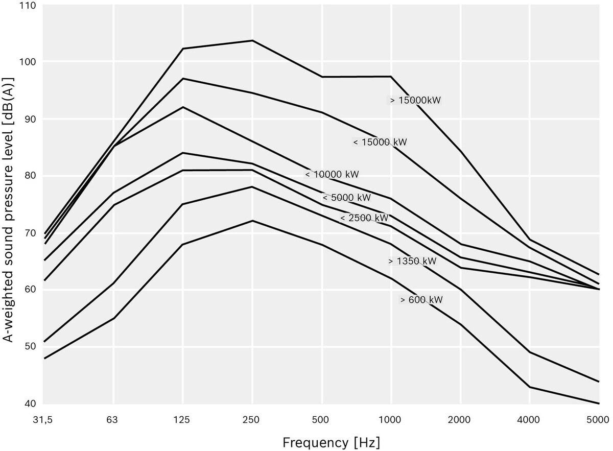
A-weighted frequency analysis and corresponding total sound pressure level as a function of the boiler heat output
|
Boiler heat output |
[kW] |
≤ 600 |
≤ 1,350 |
≤ 2,500 |
≤ 5,000 |
≤ 10,000 |
≤ 15,000 |
> 15,000 |
|
Expected value for the total sound pressure level |
[dB(A)] |
75 |
81 |
85 |
87 |
94 |
100 |
107 |
|
The values shown in the figure above (A-weighted frequency analysis and corresponding total sound pressure level as a function of the boiler heat output) are for guidance only and relate to a single boiler without a flue gas silencer. The measurement was taken at the chimney opening, 1 m away, at an angle of 45°. |
The noise generated during combustion is transmitted as airborne sound via the surface of the flue system and is emitted at the top of the chimney. The noise produced by a boiler system consists mainly of low-frequency sounds.
This noise emission can be effectively reduced through the use of flue gas silencers. In order to comply with the prescribed sound emission values, the frequency spectrum of the exhaust sound at the chimney outlet of the boiler system must be taken into account when designing a flue gas silencer.
The diagram shown in the figure (A-weighted frequency analysis and corresponding total sound pressure level as a function of boiler heat output) illustrates the average sound pressure level of a boiler, measured at the chimney opening without a flue gas silencer in the flue system. Since the combustion system (e.g. due to the burner design or the flow pattern within the combustion chamber) and the flue system (e.g. due to the number of bends, length and diameter of the flue gas line) have a significant influence on the resulting values, only indicative values for the sound pressure level can be provided here. In the case of a multi-boiler system, the noise levels of all boilers must be added together.
When planning the flue gas line, it is important to bear in mind that, depending on the requirements, a considerable length of silencer may be necessary to reduce noise emissions; this must be installed either inside or outside the installation room before the flue gas enters the chimney.
Where there are strict requirements regarding noise emissions, e.g. in hospital settings, it is advisable to consult a noise assessment expert when specifying the design of a flue gas silencer, given the complexity of the issue.