Equipment and control
The minimum requirements for operation and the safety equipment of steam boilers are set out in EN 12953-6. This includes the primary shut-off valves in the pipework, the safety equipment to safeguard against pressure exceedance and water shortage, heating equipment and all valves and measuring devices required for operation and control. All of this equipment requires an approval in accordance with the Pressure Equipment Directive.

Equipment of a steam boiler
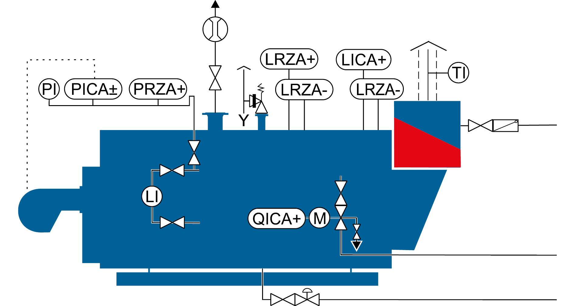
The equipment of a steam boiler generally comprises the following components:
- Steam extraction shut-off valve with steam volume measurement
- Safety valve (overpressure protection)
- Feed water shut-off valve with non-return valve
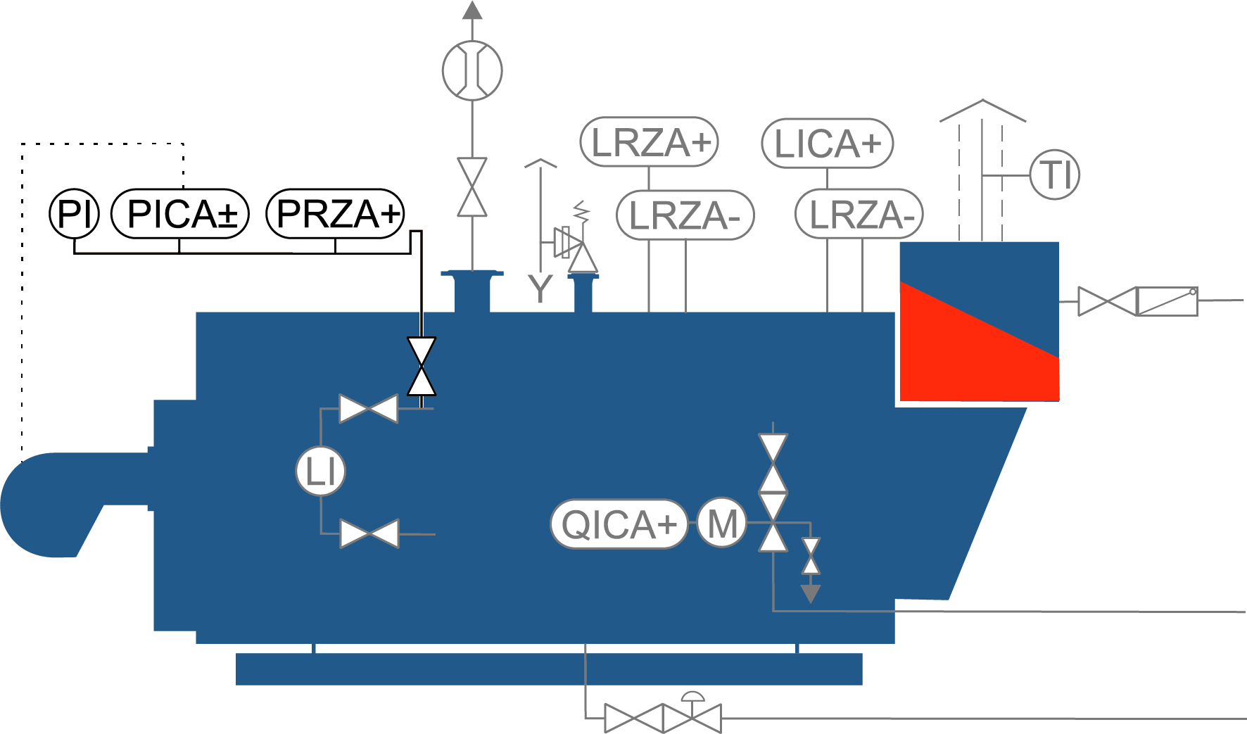
- Pressure gauge manostat bar with shut-off valve, pressure limiter (PRZA+), pressure transmitter (PICA±) and pressure gauge (PI)
- Direct level indicating device with shut-off valves
- Level measuring device with protective tube 1 with low water level limiter 1 (LRZA-) and level transmitter (LICA+)
- Level measuring device with protective tube 2 with low water level limiter 2 (LRZA-) and high water level limiter (LRZA+)
- Conductivity measurement device (QICA+)
- Surface blowdown control valve with shut-off valve
- Water sampling fitting
- Bottom blowdown quick-release valve with shut-off valve
- Flue gas temperature indicator (TI)
Additional components, such as devices for measuring the quantity of fuel, steam, feed water and the flue gas temperature, may be required to optimise operation and for possible energy management.
Output control
The steam output of boilers is generally controlled via the existing pressure in the boiler. The boiler pressure in this case is used as substitute variable for the steam quantity. If the consumers require more steam, the pressure in the boiler falls and the output control increases the heat supply or combustion output of the burner. As a basic rule, it should be observed that the burner/boiler system is a slow-response system. All control units and mixing valves that are connected to this system are adjusted to these characteristics. Under no circumstances whatsoever should attempts be made to control the pressure at the consumers or initiate measures at the boiler as this could lead to control oscillations and unnecessary loads and faults at the boiler. With consistent power consumption, correctly adjusted control and stepless burner, the combustion output required at the burner for the current rate of steam extraction is established and the boiler pressure is kept constant within reasonable limits with a deviation of ± 10% from the specified set value.
The prevailing pressure in the boiler can be read off directly at the pressure gauge (PI). The pressure transmitter (PICA+) measures the boiler pressure and converts it to a standard electrical signal (4 – 20mA). This signal is processed in the boiler control and evaluated according to the control mode. The burner is activated via adjustable switching points and set values. In this case the correct fuel-air ratio is set by the burner control.

Pressure-controlled output control of a steam boiler
|
PI |
Pressure gauge |
|
PICA± |
Pressure transmitter |
|
PRZA+ |
Pressure limiter |
Level control
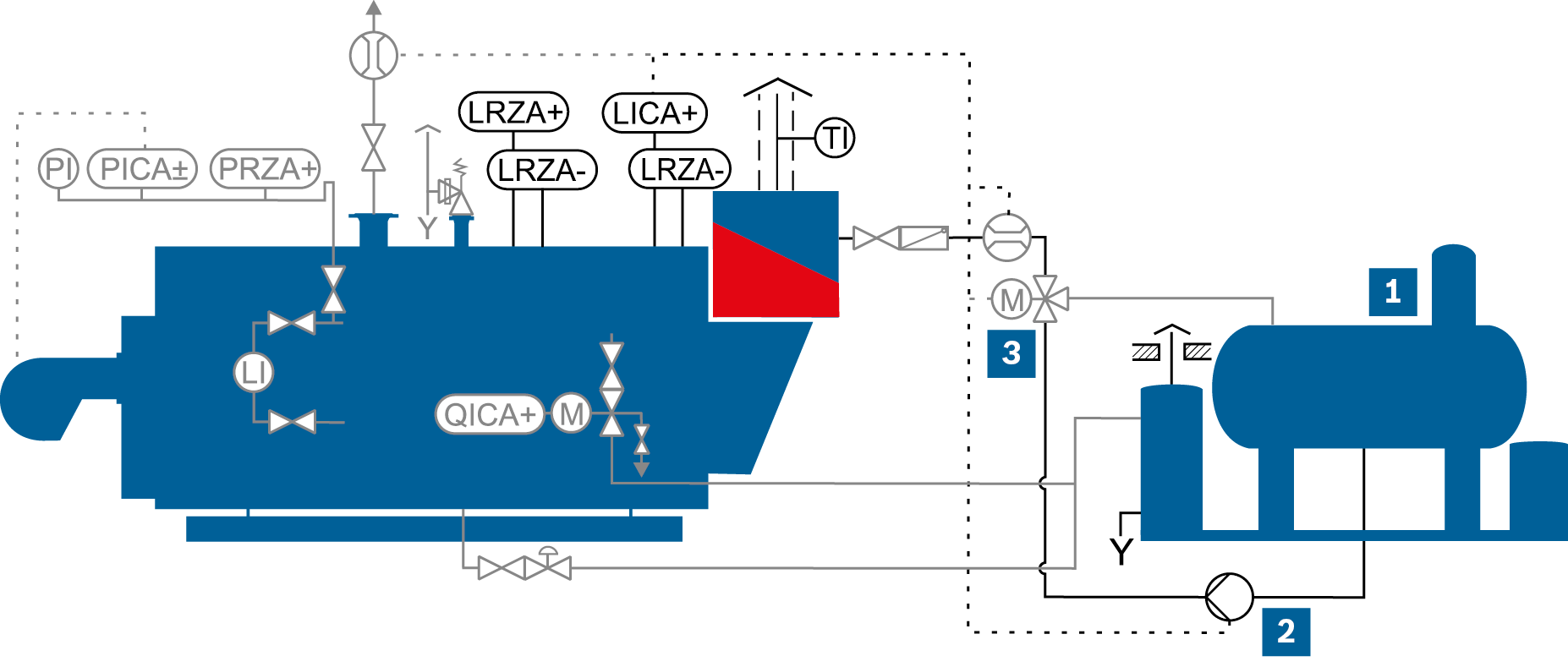
The level control in the boiler has the task of maintaining a constant water level as far as possible. Depending on the design, the water normally fluctuates between the maximum limits of 80 – 120mm. The water level in the lower range is limited visually by the low-water mark (LW) as the heating surfaces must always be underwater in order to be sufficiently cooled. The upper limit of the water level is defined by the high water mark (HW). The steam space must not be too small, as otherwise water may be carried into the steam pipe which would adversely affect the steam quality. To avoid faults and damage to the boiler or downstream consumers, the setting options in the level regulator for the average water level have been restricted at the factory. The value can only be set within the permitted range.
The prevailing water level in the boiler is continuously measured with the level transmitter (LICA+) and converted to a standard electrical signal (4 – 20mA). This signal is processed by the Boiler Control BCO and controls the feed water control valve or feed pump, depending on which equipment is selected.
A shut-off valve and non-return valve are located at the inlet to the boiler or economiser to prevent water being pushed back into the feed line. A level indicator (LI) has been installed at the boiler at the height of the water level in order to display the water level directly.

Level control of a steam boiler
|
LICA+ |
Level transmitter |
|
Feed water vessel |
|
|
LRZA+ |
High water level limiter |
|
Feed water pump |
|
|
LRZA- |
Low water level limiter |
|
Feed water control valve |
|
|
TI |
Flue gas temperature indicator |
In addition to level control, the water level is also limited via the safety chain.
|
Heat recovery with ECO |
Requirement for control characteristics |
Process characterised by rapid load changes |
Investment costs |
|
|
Continuous with control valve |
+++++ |
+++++ |
++ |
Moderate |
|
Busbar with control valve1) |
+++++ |
+++++ |
++ |
Low |
|
Continuous with IM2) |
++++ |
+++ |
++ |
Low |
|
3-component control with control valve |
+++++ |
+++++ |
+++++ |
Very high |
|
3-component control with IM |
++++ |
+++ |
+++++ |
High |
|
ON/OFF |
Not |
+ |
Very low |
Advantages and possible uses of various types of level control
1) Can only be used with multi-boiler systems
2) IM = inverter module
Modulating control with control valve
The continuous level control with control valve is still the most popular variant as it provides the benefits of fast, reliable and straightforward control.
Product: Feed water regulation module RM
Busbar switching with control valve
When busbar switching is used, several steam boilers are fed by one feed pump. In this case the water level of each boiler is controlled independently via an inlet control valve.
Modulating control with inverter module
Controlling the level via the speed control at the feed pump is the most economical variant for boiler outputs ≤ 10 t/h in terms of investment costs and operating costs.
Furthermore, it makes particular sense to use this type of level control if the boiler is run at different operating pressures (e.g. a pressure drop at the weekend) as then the benefits of the speed control with matching to the pump curve can be fully exploited.
When equipping the boiler with an economiser for heat recovery, it must be ensured that the partial load range of the burner can also be covered by the smallest frequency control range of the feed pump as otherwise there is no flow through the economiser in low-load operation which means that heat recovery cannot take place.
3-component control
When the load increases rapidly, a problem occurs as the water level initially appears to increase due to foaming of the boiler water and, although an increase in the quantity of feed water is required, this does not occur.
By continuously comparing the current measurements for steam and feed water quantities, the 3-component control can respond much more effectively to status changes.
On/Off control
On/Off pump activation is only used in a few exceptional cases and with low steam outputs up to ~ 1 t/h.
As, compared to the other control variants, the benefit in terms of investment costs is relatively low and as significantly less heat is recovered in the economiser because the pumps are frequently switched off, a continuous control often pays for itself after less than two months.
Water quality
Depending on the various physical and chemical water treatment methods, the chemical dosing for binding residual hardness and residual oxygen and the necessary alkalisation (increasing pH value in the feed water vessel), the feed water contains dissolved salts and other ingredients.
Due to the continuous evaporation process when the boiler is in operation, the residual ingredients of the feed water in the boiler water increase. The accumulation of impurities in the boiler water is particularly measurable due to the increase in conductivity of the boiler water.
To avoid the negative consequences of an excessively high boiler water salt content described below, specified limits must not be exceeded.
- Foaming of boiler water
- Water entrainment in the steam pipe
- Water level fluctuations
- Deposits in the boiler
- Corrosion in the boiler and pipework
Technical report: modern water treatment and water analysis
A certain amount of water is therefore removed from the boiler as a result of continuous surface blowdown and bottom blowdown.

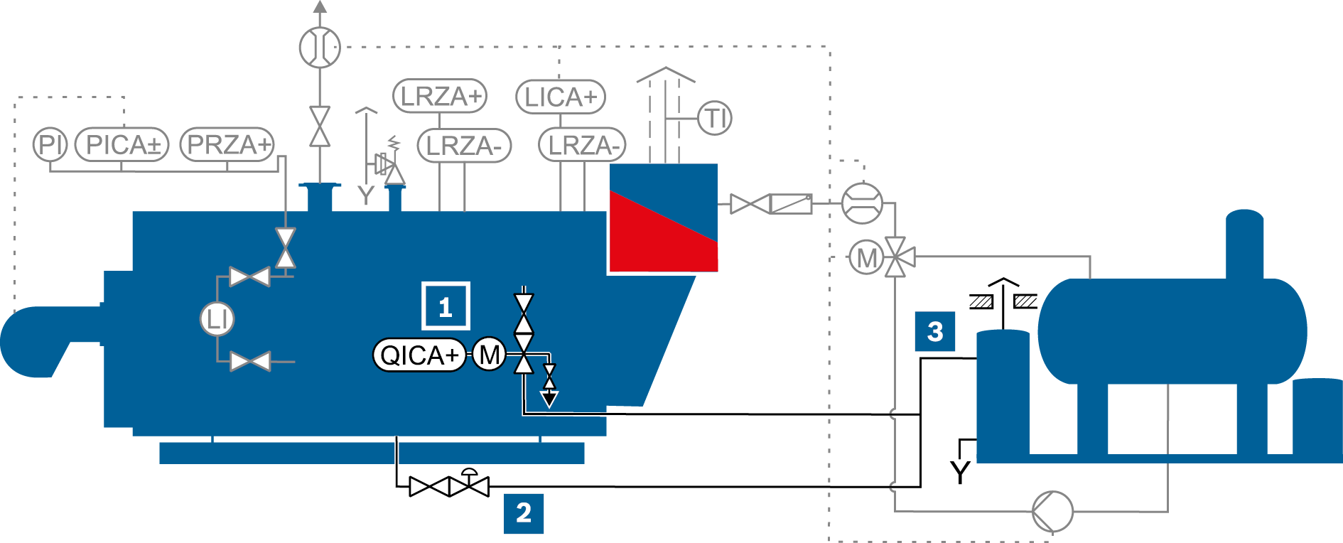
Control of the boiler water quality by means of discharge to the blowdown expansion vessel
|
QICA+ |
Conductivity transmitter |
|
Surface blowdown valve |
|
|
|
Bottom blowdown valve |
|||
|
|
Blowdown expansion vessel |
Conductivity control
The conductivity of the boiler water is measured with the conductivity transmitter (QICA+) and converted to a standard electrical signal (4 – 20mA). This signal is processed in the Boiler Control BCO, the measured conductivity displayed in the control cabinet and the actuating signal to open the motorised surface blowdown valve is generated. To allow a visual inspection to be carried out, a sight glass with non-return valve is often installed in the pipework downstream of the surface blowdown valve.
As the boiler water quality is an important factor influencing correct and smooth operation, this must be regularly checked and documented in the boiler log.
Heat recovery measures can be taken to utilise the energy content of the boiling surface blowdown water.
Info on Surface blowdown and bottom blowdown
The conductivity measured in the boiler at operating temperature is slightly higher due to the electrolytic dissociation. The conductivity sensor performs a conversion internally using the reference temperature of 25°C. This pre-adjusted conductivity is displayed at the boiler control.
In addition to electrical conductivity, the silicic acid content (SiO2) and acid capacity 8.2 value (p-value) are important factors influencing the boiler water quality. If the allowable limit of one of these variables is reached due to densification in the boiler water, this variable is definitive for the surface blowdown. However, as only the conductivity in the boiler water is measured, the conductivity reference value in the boiler water must be reduced until all limit variables can be adhered to.
Bottom blowdown control
The bottom blowdown control removes the suspended matter in the boiler water that settles on the base of the boiler. To do this, the bottom blowdown quick-release valve is opened for a few seconds at regular intervals. The valve opens abruptly which produces a local negative pressure with a suction effect that removes deposits that have accumulated on the base of the boiler from the boiler (e.g. accumulations of salts, broken down dosing agent).
The opening times of the valve during this process should be very short and be within the range of a few seconds. If the bottom blowdown valve opening times are longer, this only increases the water and energy loss from the boiler without making the bottom blowdown more effective. The bottom blowdown can be carried out manually or automatically if the boiler is not attended continuously during operation.
A manual shut-off valve is installed upstream of the bottom blowdown quick-release valve. To support the suction effect and allow boiler water that has re-evaporated to be removed, the pipework leading to the blowdown expansion vessel directly downstream of the valve should be 2 nominal diameters bigger. To avoid steam hammer, the pipework leading to the blowdown expansion vessel should whenever possible be installed without changes in height or water pockets.
Most boilers are also drained via the bottom blowdown valve.
Safety
The safety of the system is primarily ensured by proper operation, perfect functionality and maintenance of the equipment and control units of steam boilers.
To ensure safety at all times, also when the normal control units fail, limiting devices are prescribed for all steam boilers. Together with the emergency stop buttons at the control cabinet and the escape doors, these are connected in series in the safety chain in the boiler control cabinet so that when one of these elements is tripped, boiler operation is deactivated.
If one of the limiting devices is triggered, the combustion system and therefore the boiler heating is switched off and locked. In waste heat boilers, this is done by changing the flue gas dampers over to bypass or by switching off the heat-generating unit. This interlock can only be enabled once again manually on-site at the boiler. This ensures that following exceptional operating conditions the boiler attendant has identified and eliminated the cause of the fault before the boiler is brought back into operation.
Safety pressure limiter
The safety pressure limiter (PRZA+) cuts in at 95% of the maximum permissible operating pressure and switches the heating of the boiler off.
Safety valve
The safety valve must reliably prevent the maximum permissible pressure in the boiler being exceeded if the safety pressure limiter fails.
In shell boilers, this is done using direct-acting spring-loaded full-stroke safety valves with open spring bonnet.
Once the safety valve has cut in, the pressure in the boiler must fall to roughly 10% below the maximum permissible pressure before the safety valve automatically closes due to the spring tension. The subsequent pipework must whenever possible be routed directly to the atmosphere.
Level indicator – low water
The heating surfaces of the boiler must be surrounded by water at all times to ensure sufficient cooling. If the water level in the boiler falls to the extent that the heating surfaces are no longer in contact with water, there is an acute danger of overheating and possible destruction of the boiler.
One must be sure to avoid emergence of the heating surfaces, two type-tested low water indicators operating independently of one another are installed in the boiler. In steam generators, the level indicator electrode is installed in a protective tube to avoid dangerous maloperation due to foaming of the boiler water.
Technical report: history of development of water level indicators in steam and hot water boilers
Level indicator – high water
In boiler systems operated over a 72-hour period without attendance, an additional high water indicator is required so that when the highest allowable water level is exceeded in the boiler no water can be fed into the downstream steam pipes.
Conductivity limitation
The maximum permissible conductivity is also limited in boiler systems for a 72-hour period of operation without attendance to prevent uncontrolled foaming or accumulation of deposits in the boiler. When the limit is exceeded, the combustion system is also switched off in this case.
Further safety equipment
The combustion system can be shut down by other faults in addition to the limiting devices directly mounted on the steam boiler. The precise changes for the relevant fuel and the various equipment are described in the standard EN 12953 part 9.
Emergency stop
Emergency stop pushbuttons are mounted in all escape routes and at the boiler control cabinet. When an emergency stop pushbutton is pressed, the boiler safety chain is triggered. An additional emergency stop pushbutton outside the boiler house is recommended.
Monitoring of the combustion system – flame monitoring
If a flame is not detected in the combustion chamber when the fuel feed is in operation, this leads to a fault shutdown of the boiler after a few seconds. This prevents unburnt fuel forming an ignitable mixture in the flue gas system which could cause a hard ignition during a subsequent burner start.
Monitoring of the combustion system – fuel feed
The tightness of the gas shut-off valve and the minimum and maximum pressure of the fuel feed are also monitored to ensure that an ignitable mixture cannot form in the boiler or in the flue gas path.
Fig. Example showing schematic representation of gas combustion (high-pressure supply)
Monitoring of the combustion system – air deficiency safety device
Operation and function of the combustion air fan are monitored by what is referred to as an air deficiency safety device. To do so, a minimum air pressure indicator (PZA) is installed between the fan and flame head.
Steam feed
The steam feed connector with shut-off valve is located at the boiler crown. The saturated steam is fed from here into the downstream steam network. To limit noise emission, the steam feed connector must be sized so the flow speed cannot exceed ≥ 40m/s. It must also be considered that the diameter of the connector is to be sized with reference to the minimum anticipated operating pressure, as the biggest specific steam volume exists at this pressure.
A baffle plate is located underneath the connector on the inside of the boiler to ensure that small droplets carried along in the flow remain in the boiler and that the steam exiting the boiler is as dry as possible. The residual moisture content can still be as much as 3%.
To improve the steam quality, a demister made of wire mesh can also be mounted here. This can reduce the residual moisture content to roughly 0.1%.
Optional measuring equipment
Additional measuring devices, e.g. for flow-rate and temperature measurement, provide more in-depth information about operation of the boiler. These can be integrated into the control of the boiler in order to satisfy more exacting demands in relation to control quality. On the other hand, they are an important means of assessing the efficiency of the boiler operation. By acquiring, recording and evaluating this data, the operation of the boiler can also be optimised following commissioning (e.g. in the event of operational changes). Furthermore, this can therefore also satisfy the requirements arising from any existing in-house Energy Management System. The most common measurement methods are described below.
Steam volume measurement
With steam volume measurement, the steam flow delivered to the steam network is measured. In combination with a pressure or temperature measurement with saturated steam or a pressure and temperature measurement with superheated steam, the volume of steam can be converted into a steam flow and into the useful heat output delivered by the boiler.
Feed water flow measurement
During feed water flow measurement, the feed water supplied to the boiler is measured.
Fuel flow measurement
Fuel flow measurement is required for each individual boiler system in order to be able to set the maximum permissible combustion output during commissioning.
With liquid fuels, the measurement is always carried out with direct assignment to one boiler. The fuel flow rate is measured in [l/min] or [l/h].
With gaseous fuels, a measurement assigned directly to the boiler is urgently recommended. For cost reasons this is occasionally omitted and the measurement of the energy supplier in the gas transfer station is used. The measurement of the gas flow rate in [mB³/h] must subsequently be converted to [mn³/h] together with a pressure and temperature measurement for evaluation purposes.
Together with the information on the net calorific value [kWh/kg] or [kWh/l] for liquid and [kWh/mn³n] for gaseous fuels, a conversion to the quantity of energy supplied to the boiler can then be carried out and therefore used as starting basis for an efficiency calculation or to determine the annual degree of utilisation.
Flue gas temperature measurement
The flue gas temperature measurement is an important indicator of the current mode of operation of the boiler. Many optimisation options and uneconomical boiler operation or soiling of the heating surfaces can be immediately identified simply by using this straightforward low-cost measurement and by continuously recording and evaluating the flue gas temperature.


