Steam treatment, distribution and storage
Steam drying
The so-called steam quality is determined by the amount of residual moisture in the steam flow. It is advantageous if the water content is as small as possible. Steam dryers can separate the small water droplets carried along in the steam. This also removes salts or contamination they contain from the steam.
A steam baffle plate is already installed at the steam feed connector of steam boilers for this purpose. The deflection of the steam flow separates the water droplets which fall back into the water chamber. This already reduces the residual moisture content to 1 – 3% during normal operation. This is sufficient for most applications.
Further reduction in the steam moisture is only required if the load fluctuations on the consumer side are very rapid or if a super heater module is used. A demister equipped with a special wire mesh can be used for this and is also located below the steam feed connector. The residual moisture can then be reduced to roughly 0.1%.
Due to the heat losses in the steam pipe, the steam moisture along the pipework increases which is why a steam dryer can be used directly upstream of steam consumers, especially when using steam for drying purposes. In steam dryers the moist steam is admitted tangentially into the dryer and the centrifugal forces push the heavier droplets outwards against the wall where they are separated. The steam is then deflected through 180° in the bottom section where the smaller water droplets are separated and then flows out with a residual moisture content of <0.5%.
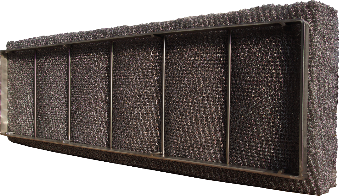
A demister, as installed in the steam boiler below the steam feed
Steam pressure reduction
A reduction in steam pressure can occur for several reasons:
- To compensate for pressure fluctuations in the steam boiler which ensures an extremely constant pressure level for the steam consumers
- To separate the boiler output control from sudden load variations at the consumer
- Consumers require different pressure levels
- The maximum permissible positive pressure of the consumers is lower than the one of the steam boiler
The steam pressure is reduced using so-called pressure reducing stations which are motor, pneumatically or medium-controlled. Medium-controlled reducing stations require no auxiliary energy or electrical components but their control quality is occasionally poorer than motor-controlled or pneumatically-controlled valves.
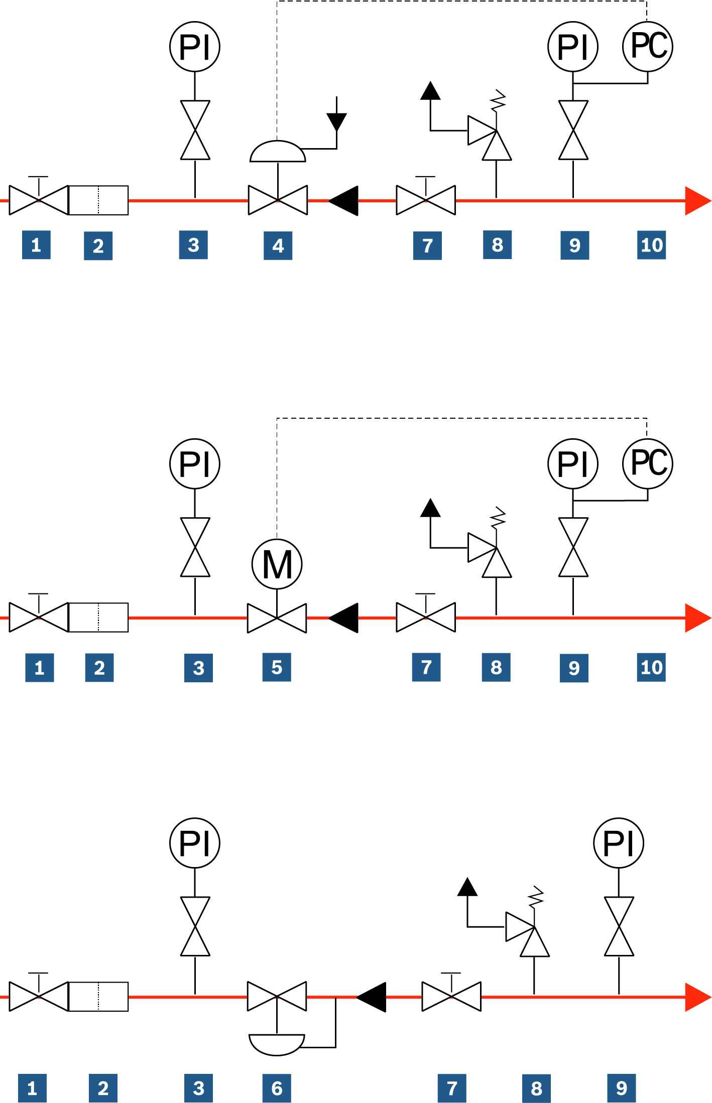
Steam pressure reducing station (pneumatically. motor or medium-controlled)
|
|
Shut-off valve (primary pressure side) |
|
|
Dirt trap |
|
|
Pressure indicator (primary pressure side) |
|
|
Control valve (pneumatically-controlled) |
|
|
Control valve (motor-controlled) |
|
|
Control valve (medium-controlled) |
|
|
Shut-off valve (secondary pressure side) |
|
|
Safety valve |
|
|
Pressure indicator (secondary pressure side) |
|
|
Pressure transmitter |
Steam distribution
Steam distributors are used to combine the steam generated by one or several boilers in a central location (normally the boiler house) then distribute it among the various consumers at the operating premises, as well as the feed water heating.
The steam is also dried, i.e. the residual moisture content reduced, due to the 180° deflection of the steam between the generator and consumer.
The pressure at the steam distributor is also normally measured for the purpose of pressure-controlled boiler sequence control.
Benefits:
- Combining of the steam from the steam generators
- Distribution among the consumers
- Control of boiler sequence control
- Steam drying and dewatering
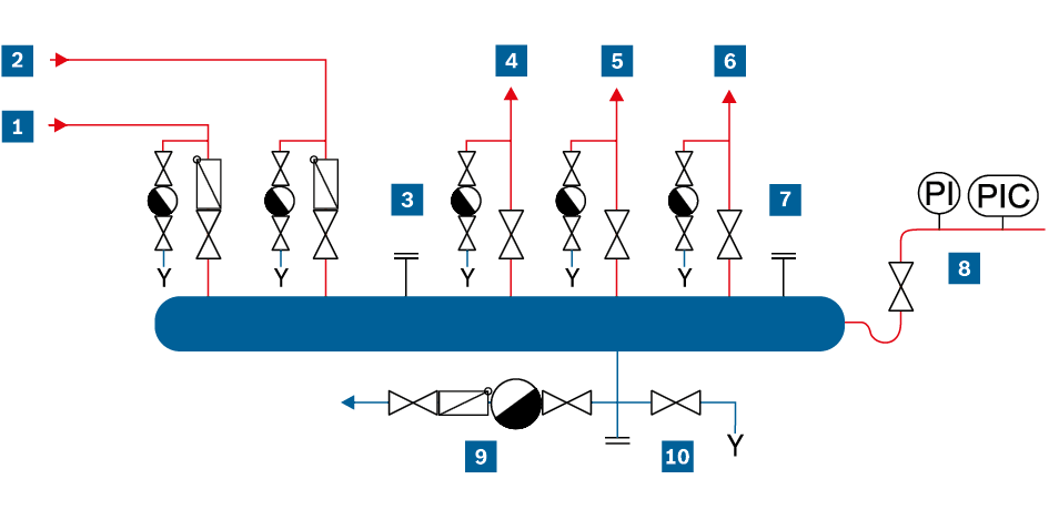
Schematic representation of a steam distributor
|
|
Supplying steam pipe from boiler 1 |
|
Outgoing steam line to feed water deaeration |
|
|
|
Supplying steam pipe from boiler 2 |
|
Reserve connector for additional consumer |
|
|
|
Reserve connector for additional boiler |
|
Manostat tube with pressure indicator (PI) and pressure transmitter (PIC) |
|
|
|
Outgoing steam line to consumer 1 |
|
Condensate pipe to condensate tank |
|
|
|
Outgoing steam line to consumer 2 |
|
Drain |
Steam storage
The purpose of the steam accumulator is to store a limited quantity of energy which is available as expansion steam when the pressure is reduced.
The steam accumulator has the following application area:
- Provides peak load coverage when the capacity of the installed steam generators is briefly exceeded (e.g. during start-up processes of consumers, with autoclaves, a few large batch processes)
- Damping rapid load fluctuations of consumers with heavy cyclical steam demands (e.g. with short recurring steam consumption peaks, many small batch processes)
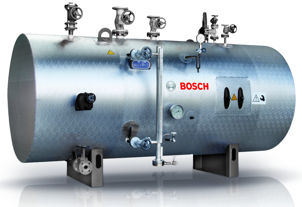
Display of a steam accumulator module |
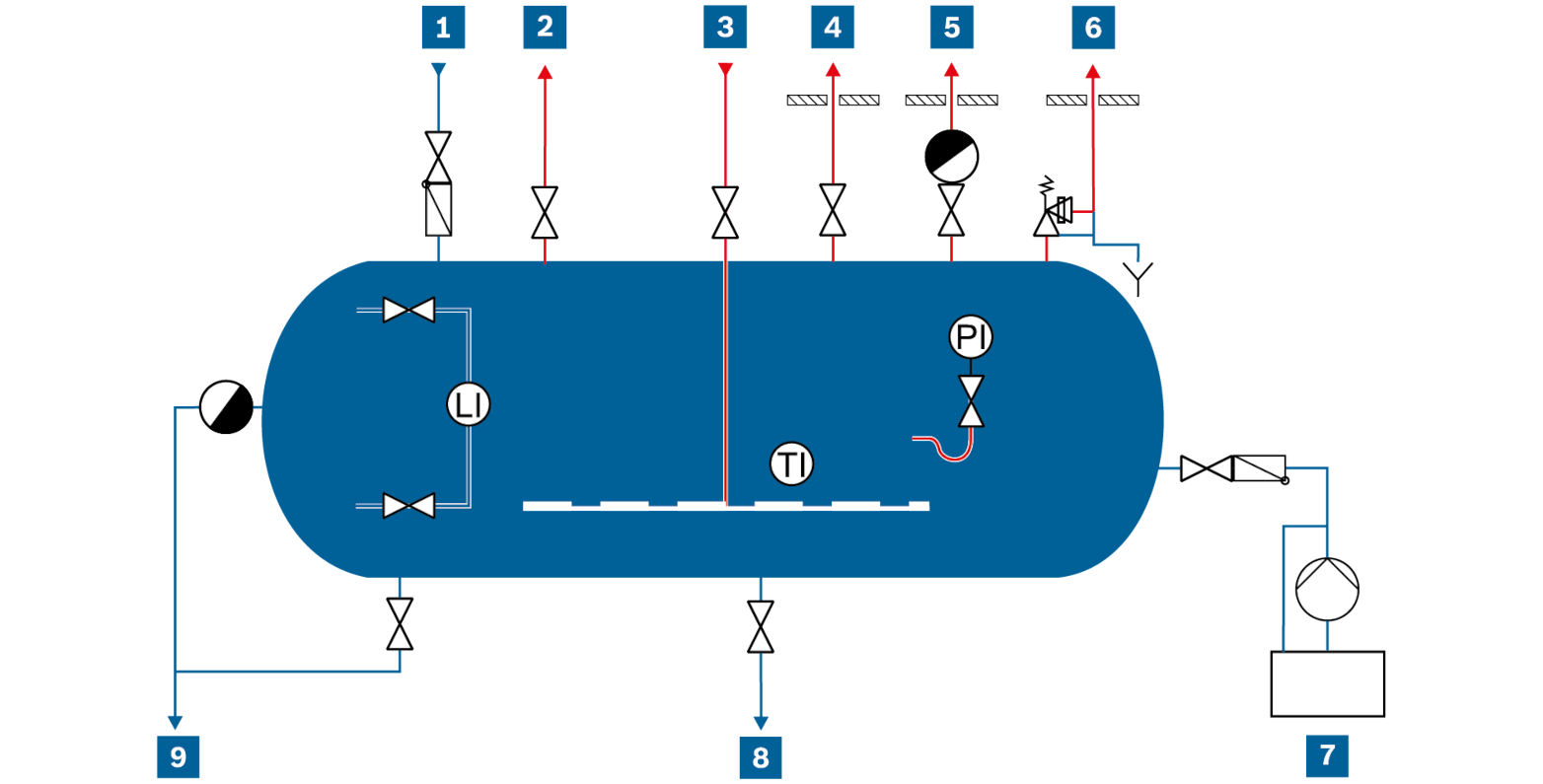
Schematic representation of pipework, steam accumulator module SAM |
|
LI |
Level indicator |
PI |
Pressure indicator |
TI |
Temperature indicator |
|
|
Feed line |
|
Start-up line |
|
Chemical dosing |
||
|
|
Steam pipe to the consumers |
|
Air vent line |
|
Water sampling line |
||
|
|
Heat-up steam pipe |
|
Pressure safeguard blow-off line |
|
Drain line and overflow |
When used correctly, a steam accumulator has the following benefits:
For the boiler:
- Reduced fluctuation of boiler pressure. This reduces the mechanical stress and increases the service life of the boiler shell
- Lower switching frequency of the combustion system. This reduces pre-ventilation losses and increases the service life of the boiler.
For the consumers:
- Covers especially high load peaks. The steam boiler can therefore be smaller
- Less water entrainment. This leads to an improvement in steam quality
The steam accumulator is a thick-walled container which is specially designed to cope with heavy pressure-change stresses. As is the case with the steam boilers, it is also subject to regular pressure testing by the approved notified body.
The steam accumulator is filled to 50% of its capacity with boiling water and is heated up to the charging pressure with steam from the boiler.
The accumulator is discharged by opening the shut-off valves on the consumer side. This reduces the pressure in the accumulator. Owing to the reduction in pressure, some of the boiling water evaporates producing what is referred to as expansion steam. The larger the water content of the accumulator and the greater the reduction in pressure the more steam will be produced.
When heating up again the same quantity of steam is supplied to the accumulator that was previously removed. It is therefore not normally necessary to supply additional feed water to the steam accumulator during operation.
The feasibility of using a steam accumulator can be investigated when planning new boiler systems and also as a retrofitting measure to improve existing processes. When using steam accumulators, special attention should be paid to overall integration into the steam system from steam boiler through to the consumer as the only way to fully reap the benefits is by ensuring optimum interaction of all components. The following figure shows which process and system parameters are decisive for the steam accumulator.
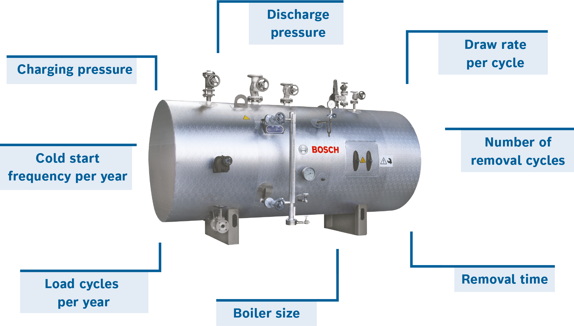
Influencing parameters in the planning and sizing of a steam accumulator
|
Exceedance of the installed output of the steam generator |
Damping of a cyclical steam demand |
|
Boiler 9,000kg/h |
Boiler 9,000kg/h |
|
Consumer peak 15,000kg/h, roughly 350kg |
Consumer peak 11,500kg/h, roughly 28kg |
|
20m³ steam accumulator filled to 65% capacity with water |
5m³ steam accumulator filled to 50% capacity with water |
|
A residual moisture content in steam of up to 5% is permitted |
Residual moisture content in steam <2% |
|
Accumulator charged after 700s |
– |
|
Accumulator charging pressure 13 bar and discharging ≤ 9.3 bar |
Accumulator charging pressure 12 bar and discharging ≤ 10.5 bar |
Examples of applications of a steam accumulator (simplified and idealised calculation)
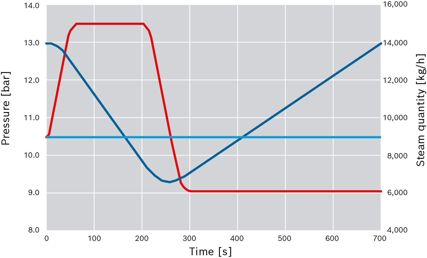
Pressure progression in a steam accumulator (example 1)
|
|
Pressure in the steam accumulator |
|
|
Steam removed by consumer(s) |
|
|
Boiler steam output |
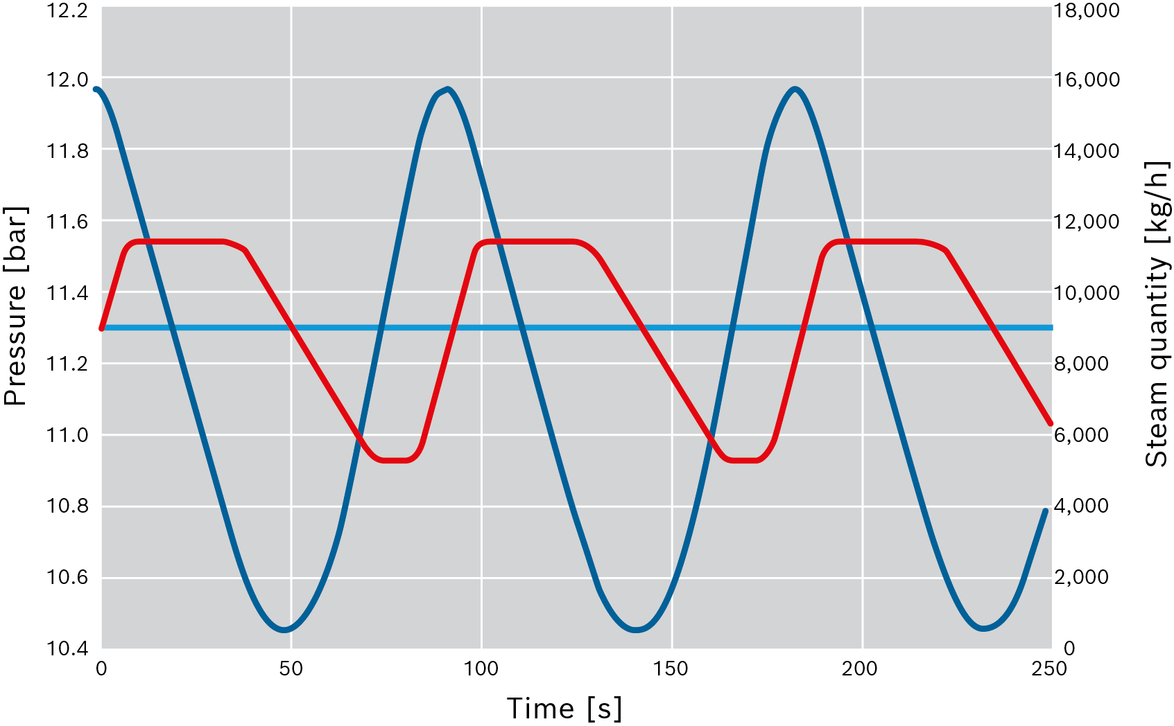
Pressure progression in a steam accumulator (example 2)
|
|
Pressure in the steam accumulator |
|
|
Steam removed by consumer(s) |
|
|
Boiler steam output |


