Peripherals
Pipework
When installing pipework systems, the terms nominal diameter (DN) and nominal pressure (PN) are used to identify characteristics of pipework for the purpose of defining compatible parts, e.g. flange connections. Nominal diameter and nominal pressure are standardised according to the geometrical increment.
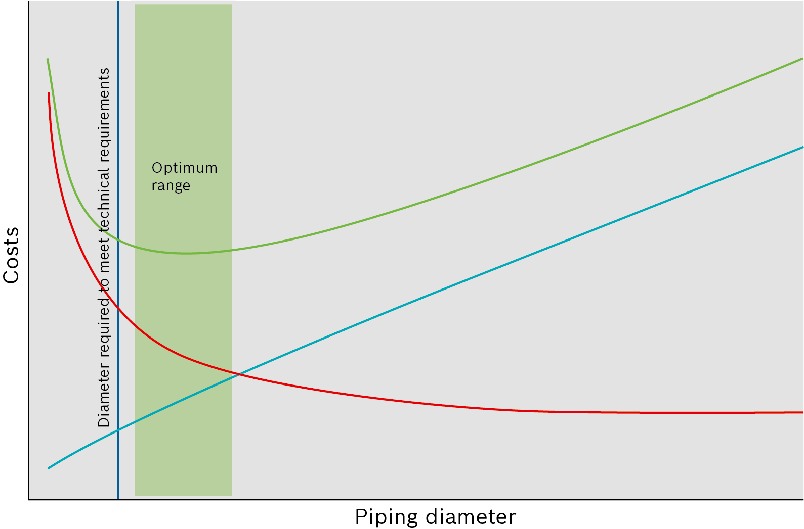
When sizing pipework, i.e. defining the nominal diameter and nominal pressure for pipework and valves, a balance must always be struck between the technical requirements, such as keeping the pressure loss or heat loss as low as possible, and the associated investment and operating costs. The optimum overall cost balance between investment and operating costs that emerges is different for every pipe and system. Owing to the curve characteristics in the minimum range of the total costs, two nominal diameters often lie within the optimum range.

Example of schematic cost trend for pipework dimensioning
|
|
Total costs |
|
|
Operating costs |
|
|
Investment costs |
The following steps must be observed when designing pipework:
- Define nominal diameter
- Define nominal pressure
- Select material
- Define spans
- Consider thermal expansion
- Take special characteristics of the medium into account during installation
As many system-specific, technical and commercial individual parameters would need to be considered for a detailed analysis, pipework is normally designed for the permissible flow speed according to economically sound principles and technical necessities based on experience. Depending on the medium and use, the recommended values have proven to be practise-compliant in many systems.
|
Medium |
Area of application |
Recommended speed |
|
Steam |
0 – 1 bar |
20 – 25 m/s |
|
1 – 40 bar |
30 – 40 m/s |
|
|
Water |
Suction line |
0.4 (0.25 – 0.6) m/s |
|
Pressure line |
2 (1.5 – 3) m/s |
|
|
Condensate |
Steam fraction |
15 m/s |
|
Water fraction |
2 m/s |
|
|
Flue gas |
16.5 m/s |
|
|
Oil |
Light fuel oil intake side |
0.5 m/s |
|
Light fuel oil discharge side |
1 m/s |
|
|
Heavy fuel oil intake side |
0.3 m/s |
|
|
Heavy fuel oil discharge side |
0.5 m/s |
|
|
Natural gas |
No specifications (design via pressure loss) |
Standard design speeds (recommended speeds) for pipework sizing
Definition of nominal diameter DN
The nominal diameters in the following table are specified without units. They correspond roughly to the inner diameter of the pipework in mm. This is for production reasons as the tools used in the manufacturing of pipes are defined via the external diameter and the clear inner diameter therefore varies depending on the wall thickness. The nominal diameter will normally suffice as calculation variable for rough sizing of the inner diameter.
|
Nominal diameter |
External diameter d1 |
Nominal diameter |
External diameter d1 |
Nominal diameter |
External diameter d1 |
||||
|
6 |
10.2 |
80 |
88.9 |
500 |
508.0 |
||||
|
8 |
13.5 |
100 |
114.3 |
600 |
610.0 |
||||
|
10 |
17.2 |
125 |
139.7 |
700 |
711.0 |
||||
|
15 |
21.3 |
150 |
168.3 |
800 |
813.0 |
||||
|
20 |
26.9 |
200 |
219.1 |
900 |
914.0 |
||||
|
25 |
33.7 |
250 |
273.0 |
1,000 |
1,016.0 |
||||
|
32 |
42.4 |
300 |
323.9 |
1,200 |
1,219.0 |
||||
|
40 |
48.3 |
350 |
355.6 |
1,400 |
1,422.0 |
||||
|
50 |
60.3 |
400 |
406.4 |
1,600 |
1,626.0 |
||||
|
65 |
76.1 |
450 |
457.0 |
Pipe diameter (EN 10255:2004+A1:2007, EN 1092-1:2013-04, Table A.1)
The necessary nominal diameter can then be calculated as follows:
To optimise nominal diameters which have been designed according to a permissible recommended speed, it may be advisable in individual cases, e.g. if the pipework is very long, to recalculate and optimise the nominal pipe diameter using special design programs.
Defining the nominal pressure PN
The nominal pressure is a standardised pressure stage for pipework and valves. It represents a parameter for the mechanical and dimensional characteristics of a component. Components with the same nominal diameter and same nominal pressure are compatible. The nominal pressure corresponds the maximum permissible positive pressure [bar] at a reference temperature of 20°C.
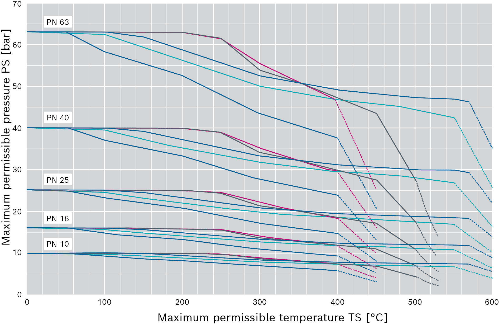
However, in addition to the material, the maximum permissible positive pressure of a component depends first and foremost on the temperature. At higher temperatures, the maximum permissible operating pressure falls below the nominal pressure. Pipework or valves can then not be operated at the nominal pressure.
The pressure-temperature assignment of flanges is based on the material groups. The following materials and groups are customary in the area of steam boilers:
|
Material group |
Material type |
Material number |
Material |
|
3E0 |
Unalloyed steels with guaranteed strength characteristics at higher temperatures |
1.0352 |
P245GH |
|
3E1 |
Unalloyed steels with defined characteristics ≤ 400°C, upper yield point > 265 N/mm² |
1.0460 |
P250GH |
|
4E0 |
Low alloy steels with 0.3% molybdenum |
1.0426 |
P280GH |
|
12E0 |
Standard carbon content, stabilised with Ti or Nb |
1.4541 |
X6CrNiTi18-10 |
|
15E0 |
Standard carbon content, alloyed with molybdenum, stabilised with Ti or Nb |
1.4571 |
X6CrNiMoTi17-12-2 |
Material groups according to EN 1092-1:2013-04 Table 9, G.2.2, G.3.2, Table D.1
The following diagram shows the pressure-temperature curves for different nominal pressure stages. In this case also observe the information in the chapter Tools – Pressure-temperature assignment, which contains the tables for the diagram.

Pressure-temperature assignment for flanges according to EN 1092-1
|
|
3E0 |
|
|
3E1 |
|
|
4E0 |
|
|
12E0 |
|
|
15E0 |
Defining the material
The following table states only the minimum requirement for material selection. Other materials can be also used where special installation conditions, customer requirements or national or local regulations apply.

|
Materials containing copper must not be used for any pipework to and from the steam boiler, in the condensate and make-up water area. |
|
Application area |
Pipework material |
|
Steam pipes |
Steel or stainless steel with inspection certificate |
|
Feed water lines |
Steel |
|
Safety valve blow-off pipes |
Steel |
|
Ventilation and drain lines |
Steel |
|
Seat drainage (safety valve) |
Copper or stainless steel |
|
Softened water |
Plastic (cold) or stainless steel (following heating) |
|
Osmosis water |
Stainless steel |
Minimum requirement for material selection
Definition of spans
It must be ensured through a sufficient number and correct construction of holders that pipework does not deform beyond acceptable limits due to weight forces (own weight, content, valves and insulation) and other forces acting on it (e.g. at deflections).
Requirements for pipework are explained in EN 13480-3.
Pipework and flanges for water and steam
|
|
|
PN 40 |
Max. span |
|
10 |
17.2 |
2.0 |
– |
|
15 |
21.3 |
2.0 |
– |
|
20 |
26.9 |
2.3 |
– |
|
25 |
33.7 |
2.6 |
2.9 |
|
32 |
42.4 |
2.6 |
3.2 |
|
40 |
48.3 |
2.6 |
3.5 |
|
50 |
60.3 |
2.9 |
3.9 |
|
65 |
76.1 |
2.9 |
4.7 |
|
80 |
88.9 |
3.2 |
5.4 |
|
100 |
114.3 |
3.6 |
6.2 |
|
125 |
139.7 |
4.0 |
6.9 |
|
150 |
168.3 |
4.5 |
7.5 |
|
200 |
219.1 |
6.3 |
8.6 |
|
250 |
273 |
7.1 |
9.7 |
|
300 |
323.9 |
8.0 |
10.6 |
|
350 |
355.6 |
8.8 |
11.1 |
|
400 |
406.4 |
11.0 |
11.8 |
|
500 |
508 |
14.2 |
12.5 |
|
600 |
610 |
16.0 |
13.2 |
1) Requirements for span L1:
– According to EN13480-3:2014 – filled with water, thickness of insulation 80mm
– With additions through interpolation
– L1 limitation of deflection, up to DN 50 = 3mm deflection, from DN 65 = 5mm deflection
– For details see EN13480-3
Thermal expansion
Substances expand when they are heated and contract when they cool down again.
This effect must be taken into account at many points in a boiler system, especially in locations where high temperatures can occur during operation.
The following points must for example be taken into account during planning and installation:
|
Location |
Use of – to absorb the elongation |
|
Piping
|
Pipework compensators
|
|
Boiler and container |
Friction bearings on feet and base frame Expansion joints and expansion legs on incoming and outgoing pipework |
The following equation can be used to calculate the linear thermal expansion:

|
Expansion coefficients of different steels Low alloyed steel (ferritic): Stainless steels (austenitic): |
The leg length required to absorb thermal expansion must be determined according to the general codes of practise.
Minimum distance to structure and adjacent pipework
A clearance of at least 50 – 100mm should be maintained in order to install the pipework and insulation and also carry out repairs. The frequently used technical standard for insulation work DIN 4140 recommends a minimum clearance of 100m.
To minimise the clearances, flange connections should have an offset arrangement on pipe bridges.


