Installation
When positioning the boiler house on the operating premises, the following requirements, among other things, must be taken into account:
- Fuel supply and storage
- Space requirement for the boiler house and flue
- Possibility of system expansion
- Noise emissions (especially for neighbours)
- Position of production facilities on the operating premises (shortest possible routes to consumers)
- Fire zones
- Architectural and design aspects
Some of these requirements cannot be fully satisfied all at once, especially in companies that have evolved over a long period of time. The location will therefore not necessarily be ideal for all requirements and instead represents a compromise between the operational and technical requirements and cost effectiveness.
Installation room
A number of basic requirements for the boiler installation room are dealt with below. This information is provided purely to assist with planning. Furthermore, all relevant local and national regulations and applicable standards must be observed.
Fundamental requirements
The installation room must meet the following requirements:
- The boiler installation room has to be kept clean and free of dust and dripping water.
- The room temperature must be between 5°C and 40°C.
- Entry to the boiler installation room by unauthorised personnel is forbidden.
- One must ensure that sound insulation measures comply with local regulations.
- The control cabinets must be installed in such a way that they are not exposed in any manner whatsoever to vibrations or shaking of system components.
- The control cabinets must be installed in areas where they will be protected from impermissible heat radiation and can be safely accessed even in potentially dangerous conditions.
- Compressed air supply for bottom blowdown and any further pneumatic actuators, if necessary, should be available.
- Escape possibilities with emergency stop buttons, located opposite one another whenever possible, must exist.
- It must be ensured that lighting is sufficient, especially in the area of the valves and safety devices.
- Fixing options for pipework should be available on walls and ceilings.
- Every boiler installation room should have a continuous or nearly continuous, free external wall or ceiling area of at least 1/10 the floor area (or as per local regulations), that will yield much more easily than the other surrounding walls if excess pressure occurs in the boiler installation room. The relevant national and local regulations and applicable standards must be observed when defining the pressure relief surface.

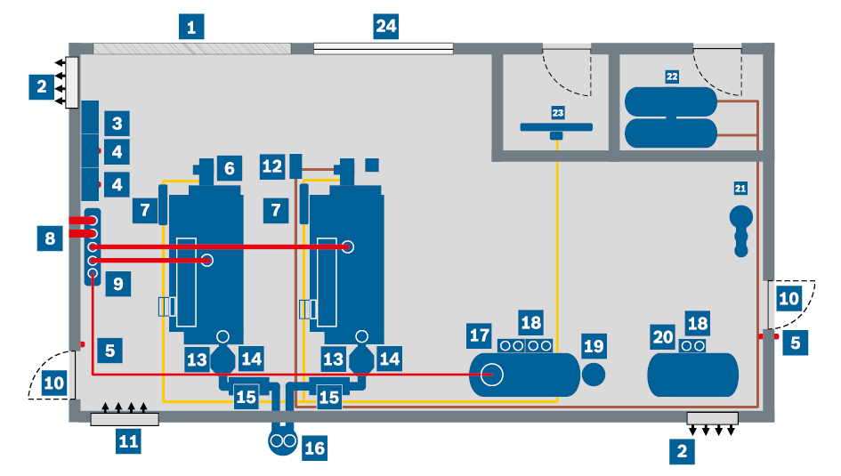
Example of a boiler house (simplified representation)
|
|
Fitting clearance |
|
Integrated economiser ECO |
|
||||||||
|
|
Extract air (top) |
|
Condensing heat exchanger |
|||||||||
|
|
System Control SCO |
|
Silencer |
|||||||||
|
|
Boiler Control BCO |
|
Chimney |
|||||||||
|
|
Emergency stop button |
|
Water service module WSM |
|||||||||
|
|
Boiler |
|
Pump module PM |
|||||||||
|
|
Gas regulation module GRM |
|
Expansion vessel BEM |
|||||||||
|
|
Steam pipe, consumer |
|
Condensate service module CSM |
|||||||||
|
|
Steam distributor SD |
|
Water treatment module WTM |
|||||||||
|
|
Escape route |
|
Oil tanks |
|||||||||
|
|
Supply air (bottom) |
|
Gas transfer station |
|||||||||
|
|
Oil supply module OSM |
|
Pressure relief area |
Accessibility
The boiler and system components should be arranged so that the mounted valves, sensors and all inspection apertures are still accessible. It only makes sense in some respects to position the boiler and also several system components on a wall. A clear route at least 1m wide, especially on the operating side of the boiler and the components, should be allowed for. It must also be ensured that surfaces that can be walked on are high enough.
Foundation and installation
It must be ensured that the following requirements for the foundation and installation are met:
- It has to be ensured that the floor at the installation location is perfectly level (evenness tolerance with reference to DIN 18202) and has sufficient load-bearing capacity.
- When calculating the load bearing capacity of the foundation, the maximum operating weight of the components concerned must be taken into account. When determining the operating weight, additional components (e.g. control cabinet, burner, silencer, exhaust pipes) and their cumulative weight must be taken into account. The operating weight is the weight of the components when filled.
- Existing floor channels must be covered and equipped with drainage facilities.
- The entrance to the boiler installation room must be designed according to the dimensions of the individual components. Suitable lifting gear must be provided at the boiler installation room to move heavy equipment.
- If the installation location needs to be separated from the system to reduce structure-borne noise, sound insulating strips must be placed underneath before installing the system.
Supply and extract air apertures
The supply air must be free of foreign substances and must not contain dusts or corrosive or explosive components, such as solvents or refrigerants. With heat recovery boilers in combination with the unit generating the waste heat (combined heat and power unit or gas turbine) additional notes of the manufacturer of the unit producing the waste heat gas must be observed.
If the ventilation through the boiler house is insufficient or the combustion system air required is drawn in independently of the room air (e.g. via air conduits from other rooms or from the atmosphere), one or several CO monitoring device(s) must be provided in the boiler room.
The supply air aperture should ideally be located in the area at the rear of the boiler. If this is not possible for structural reasons, install baffles or sheet metal channels inside the boiler installation room to deflect the inlet air. When planning the supply air apertures, the arrangement of frost-sensitive (e.g. water treatment) system components which cannot be installed directly in the flow of supply air must also be taken into account.
Extract air apertures must also be provided. Their purpose is to remove the heat underneath the ceiling that accumulates even when heat loss in the boiler house is low.
Supply air apertures should be fitted 500mm above the boiler room floor; extract air apertures should be fitted at the highest point of the installation room. Cross-ventilation should also be ensured in this case.
Supply and extract air apertures have to be sized appropriately to obtain a pressure of ±0mbar in the boiler installation room. The calculation formulae below should be regarded as a non-binding recommendation. It is essential that the system installer seeks the agreement of the responsible approval or building control authority. Additional consumers of supply air (e.g. compressors) have to be taken into account when sizing.
|
Group |
Limits |
Supply air cross-sections (formula) |
|
Sz 1 |
Q· ≤ 2,000 kW |
FGR 1 = 300 + (Q· – 50) ∙ 2.5 |
|
Sz 2 |
2,000 kW < Q· ≤ 20,000 kW |
FGR 2 = 5,175 + (Q· – 2,000) ∙ 1.75 |
|
Sz 3 |
20,000 kW < Q· |
FGR 3 = 36,675 + (Q· – 20,000) ∙ 0.88 |
| FGR | Clear flow cross-section [cm²] |
| Q· | Thermal output |
The side ratio should not be more than 1:2. Each of the required extract air cross-sections correspond to 60% of the supply air cross-sections.
The specified cross-sections must be planned as clear openings (net cross-sections). Shading by grilles or louvres must also be taken into consideration.
If the combustion air is routed via air inlet channels to the burner, an optimised flow path and adequate sizing with regard to the pressure loss have to be ensured. The pressure loss must be taken into consideration in the combustion design. Any condensate that accumulates in the air intake ducts must be removed before the combustion air fan.
Pipework
Pipework must be designed in accordance with national and local regulations and the applicable standards, taking the resulting pressure losses and flow speeds into account.
For guide values on sizing, selection of materials and many more aspects, refer to the chapter Technology.
Installation conditions
Installation conditions such as installation altitude, coastal location, general construction conditions and/or electrical supply have a significant effect on the design of the steam boiler system.
The installation altitude, for example, affects the ambient pressure and the airtightness affects the design of the combustion air fan. Additional aspects such as reduced motor cooling with pumps must be taken into account at very high installation attitudes of >1,000m.
The salty air in coastal regions promotes corrosion, which affects the burner and chimney materials, for example.
The electrical supply (voltage and frequency) must be taken into account at the control cabinet and motors (e.g. of fans, pumps and valves).


