Increasing efficiency at the burner system
Combustion air fan
An optimum fuel/air mixture is required to achieve full combustion. However, industrial boiler systems are often run in partial load operation. In this mode of operation both the fuel and air supply are reduced.
The combustion air fan without speed control also runs in partial load ranges at nominal speed because in this case the air quantity supplied for combustion is restricted purely by closing air dampers. In this case the fan consumes a large amount of electrical power which disappears with no benefit due to the restriction. If the quantity of air is primarily modified through modulation of the fan speed, the power consumption in partial load ranges is reduced (roughly 40% can be potentially saved).
The noise generation behaviour is also along the same lines as the reduction in power consumption. All systems that are often operated in partial load ranges for extended periods should be equipped with speed-controlled fans.
Around 40% of the electrical energy can be saved by using a burner load profile with medium capacity utilisation. This normally achieves annual savings amounting to a four-figure Euro sum which means that a speed-controlled burner normally pays for itself within a year.
|
Example: |
|
|
Boiler output |
10 t/h |
|
Burner fan |
22 kW |
|
Electricity savings |
around 48,000 kWh/a (42 %) |
|
Cost savings |
around 6,720 €/a (with electricity price 0.14 €/kWh) |

Energy savings with speed-controlled burner fan
Excess air
In combustion technology, the ideal situation is stoichiometric combustion. This happens if all fuel molecules react completely with the oxygen without leaving any unburned fuel or oxygen behind.
If insufficient atmospheric oxygen is supplied during the combustion process, an incomplete combustion reaction may occur. A negative consequence of this would be the formation of carbon monoxide, a highly poisonous gas. If the quantity of air is increased too rapidly, all fuel molecules have already reacted with the oxygen molecules. The remaining oxygen molecules form a surplus which is not required. As the cold ambient air is normally used as combustion air, this cold air is ultimately heated with an unnecessarily high volume of excess air, which is released into the atmosphere together with the flue gases.
An optimum combustion air setting is therefore important for efficient operation and safe, clean combustion. This is attributable to air pressure, air temperature and air humidity fluctuations on the one hand and fluctuations in the fuel quality, which will increase. On the other hand, a certain amount of excess air compared to the theoretical ideal must be specified to provide a margin of safety. Ultimately, carbon monoxide, a poisonous and explosive gas, must not be allowed to form under any circumstances. These settings are normally carried out and checked when commissioning the boiler system and when carrying out quarterly or six-monthly maintenance.

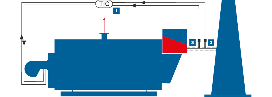
O2 and CO control at steam boiler (simplified representation)
|
|
Control |
|
|
O2 test probe |
|
|
CO test probe |
|
|
Steam |
|
|
Flue gas |
In order also to be able to operate the systems closer to the optimum operating point under varying conditions, continuous measurement and control units are required. An O2 control essentially consists of an oxygen measurement probe which is installed in the flue gas flow and a control unit. This continuously records the residual oxygen content in the flue gas and forwards the signal to the burner control which adjusts the air quantity as required.
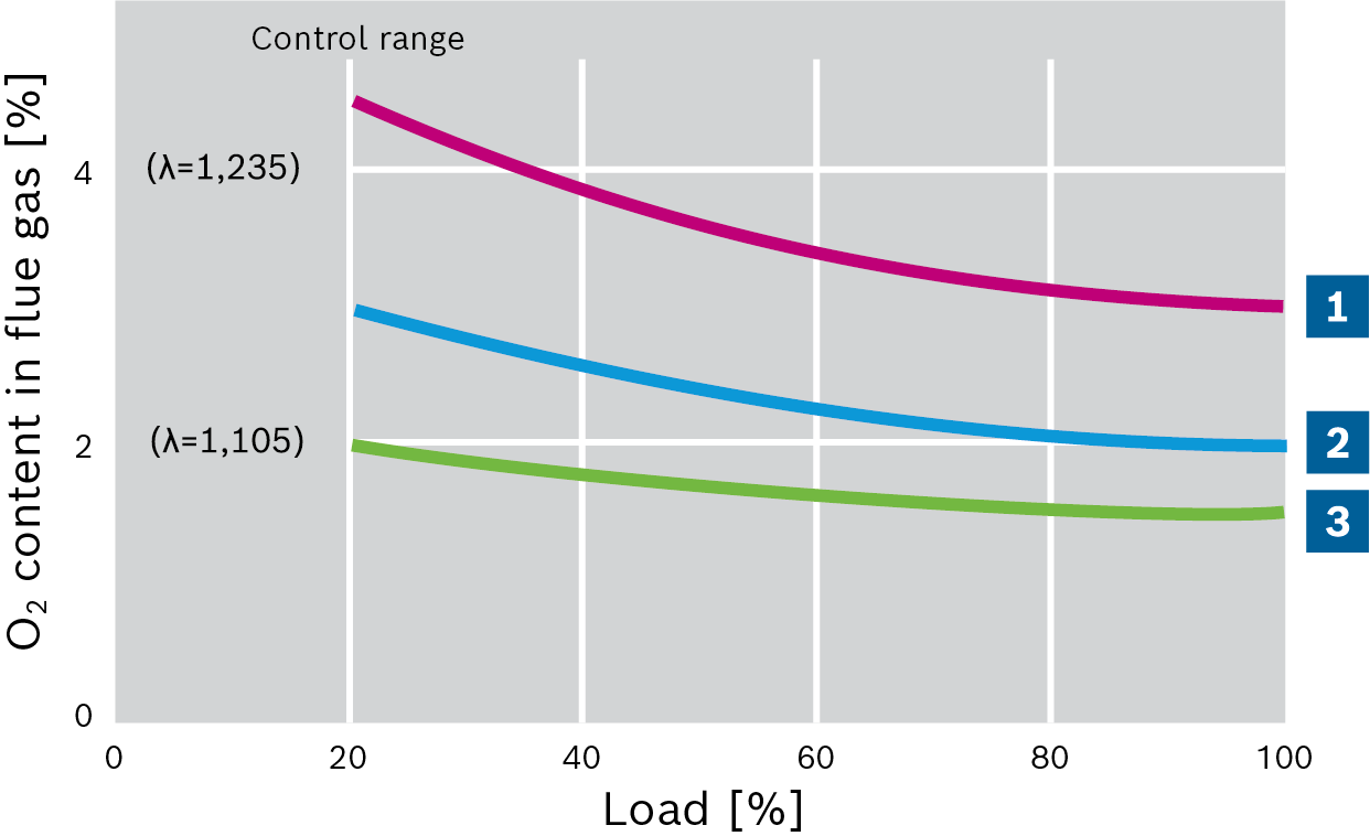
Combined electrodes (O2 and CO) have been available for a number of years. In combination with CO measurement, the excess air λ can be set more precisely at the CO limit. When using an O2 and CO control, the setting normally used for excess air at full load of 3 – 4% by vol. of oxygen in the flue gas can be reduced to 0.5 – 1.0% by vol. of oxygen. This equates to a flue gas loss reduction of roughly 1 percentage point at the same flue gas temperature. CO control cannot be used when using oil as the fuel.

Residual oxygen content and excess air using O2 and CO control via the burner load
|
|
Without control |
|
|
With O2 control |
|
|
With CO control |
Output adjustment
In existing systems, and also occasionally new systems, the available boiler output is far greater than the actual steam output required.
The causes of this are frequently:
- Reduction of demand in existing systems, e.g. because consumers no longer exist or the existing potentials for heat recovery have subsequently been tapped
- Oversizing during the planning of new systems, e.g. due to incorrect diversity factors of consumers, taking power reserves that are far too high into account or expansion of the consumers that has already been considered but not yet implemented
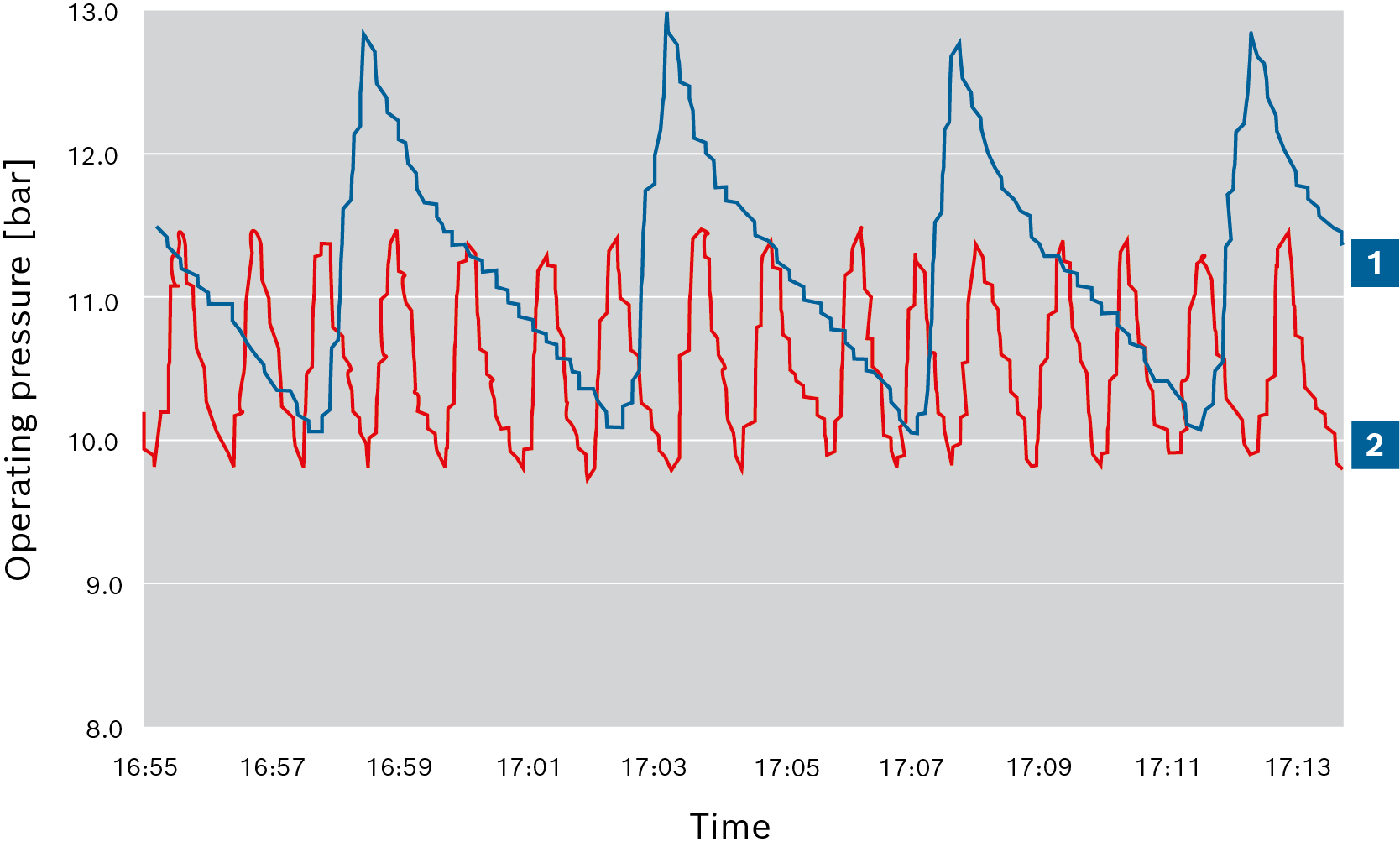
As a consequence, the rate of steam extraction is too low in relation to the boiler output, which leads to a high number of burner switch-on and switch-off operations. This causes pre-ventilation losses and also stresses due to temperature fluctuations that can be extreme, especially with long pre-ventilation times.
The following measures can be taken to compensate for an overly high boiler output:
- Installation of low load controls that postpone immediate up-regulation following the burner start
- Use of power controllers that allow the burner to adhere to the low-load stage for an unlimited period
- Use of burners with high control range
- Matching of burner output to the actual requirements. This requires modification of the burner or addition of a burner with a smaller output range

Pressure curve before and after adjustment of the burner output
|
|
Pressure curve before adjustment |
|
|
Pressure curve after adjustment |
Pre-ventilation
Before every burner start it must be ensured that there are no ignitable mixtures in the flue gas paths. This is achieved in practise by pre-ventilation. Before the burner ignites the flame, the combustion air fan starts and pushes ambient air through the hot flue gas paths which are still at boiling temperature. This heats the cold air and draws heat from the boiler. A sufficient air change-over is prescribed which can lead to a significant energy loss, especially with frequent burner starts.
As a rule, the pre-ventilation time must be sized so as to achieve a 2 – 3-fold air change, with reference to the entire flue gas system. The design must be agreed with the technical supervisory authority. Frequent burner starts are not only uneconomical, they also have a detrimental effect on the service life. An ideal situation to aim for would be 1 – 2 burner switch-on cycles per hour. If there are more than 4 burner switch-on cycles per hour, measures should be taken to reduce the number of burner switch-on cycles, e.g. by adjusting the output of the burner.


