Components
Combustion and heating
The purpose of the combustion system is to turn the carbon, hydrogen and possibly sulphur in the fuel completely into CO2, H2O and SO2. So that combustion is as clean as possible, the correct mixture ratio of fuel and combustion air must be present at the right time and place in the combustion chamber.
Pressurised combustion is almost exclusively used for this in shell boilers. This means that the combustion air fan must provide the positive pressure necessary to overcome the 5 – ≤ 50 mbar resistance caused by the boiler and, if installed, the downstream heat exchanger. A slight positive pressure therefore always exists in the combustion chamber.
Technical information: requirements for an on-site burner system
Fuels
Natural gas and fuel oil are still the most commonly used fuels. Depending on the mode of operation of the steam boiler, the required output or emission level requirements, each of these standard fuels offer different benefits and are suitable for different applications.
Info on Criteria for selection between fuel oil and natural gas
The correct combination of fuel, combustion equipment and combustion chamber is particularly decisive for the cleanest possible combustion.
In addition to the standard fuels, different gaseous and liquid fuels can also be used in shell boilers. Depending on the fuel, this is easy to implement or may require a great deal of effort. Whatever the case, use of these fuels should be carefully considered in the project phase as, in addition to higher investment, stricter monitoring and maintenance during operation is sometimes required.
Examples of liquid special fuels:
- Biodiesel
- Animal fat
- Rapeseed oil
- Soya oil
- Palm oil/grease
Examples of gaseous special fuels:
- Biogas
- Bio-natural gas
- Sewage gas
- Gas from biomass gasification
- Hydrogen enriched natural gases
Combustion of these fuels can take the form of individual auxiliary fuel combustion, e.g. when using a dual-fuel burner with natural gas and a liquid special fuel, or as proportioning combustion, e.g. natural gas with biogas.
Fan variants of combustion systems
Monoblock burner
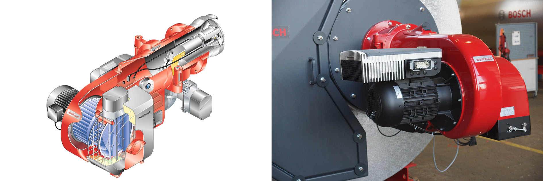
Sectional representation of monoblock burner (Weishaupt)
Combustion systems in which the combustion air fan is directly integrated into the casing of the burner are referred to as monoblock or pressure-jet burners. This burner system is suitable for fuel oil, gaseous fuels and also as a combination system in which a straightforward changeover between gas and oil combustion is possible. The most obvious advantage of monoblock burners is their compactness and therefore favourable design, and also that all systems in the combustion system can be mounted directly at the boiler in a space-saving manner. Monoblock burners can be used up to a combustion output of roughly 10MW. They are however not suitable for use with an air preheating system.
Duoblock burner
The term duoblock burner is used to describe burners whose combustion air fan (shown mounted on the boiler) and combustion unit are installed separately. The combustion air fan and burner are connected by a combustion air duct. Duoblock burners are used specially for large combustion outputs and when using air preheating.
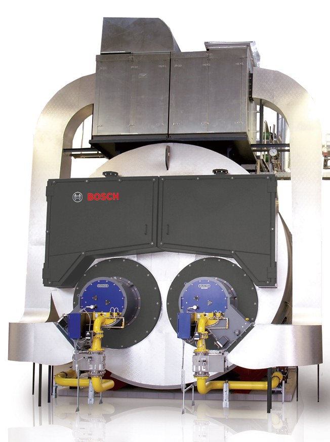
Duoblock burner with fan on the boiler crown and combustion air ducts (Saacke)
Combustion systems for liquid fuels
The most important terms and distinguishing features for combustion systems and the necessary equipment are described below.
Pressure atomiser
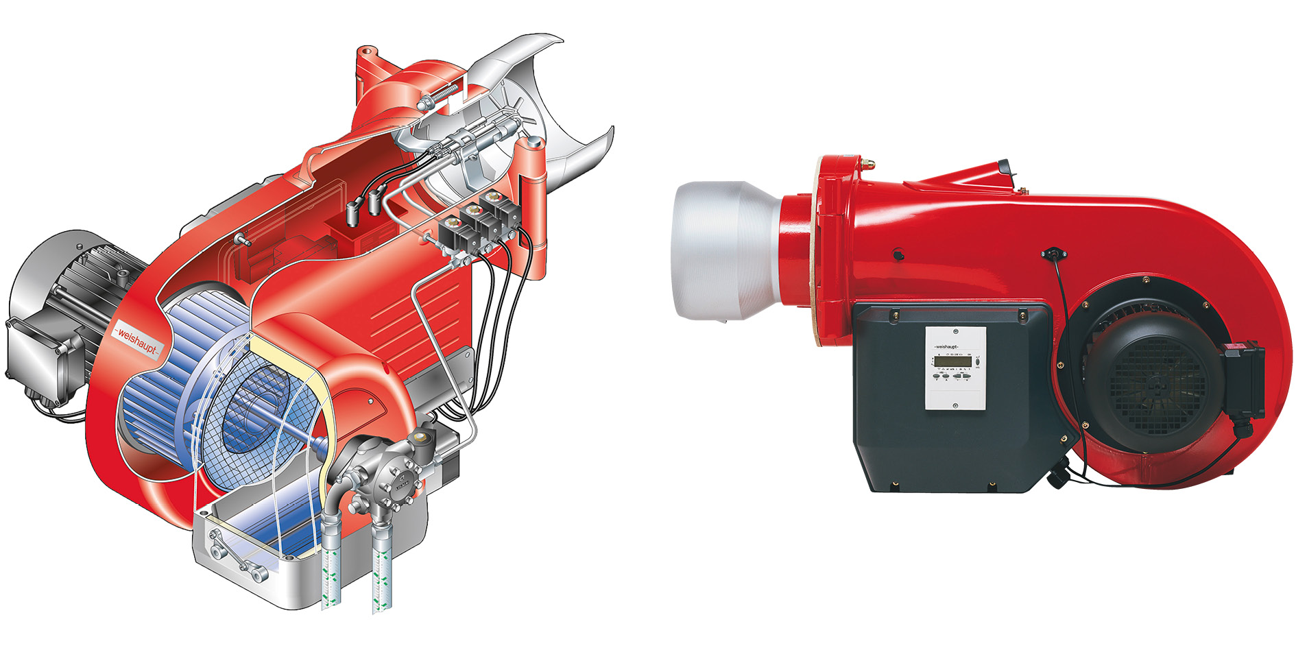
Image and sectional representation of oil burner (Weishaupt)
With pressurised atomisation, the oil is guided through a nozzle and discharged as a fine spray into the combustion chamber. The pre-charge pressures in the oil infeed must be roughly 6 – 30 bar. When the oil jet exits from the nozzle, fine oil droplets with a large reaction cross-section form. The prerequisite for this is that the viscosity of the fuel must be within the range of 5 – 8mm²/s. If this is not the case at ambient temperature, the oil must be preheated.
The burner can be controlled in different ways. With step burners, several nozzles are installed in the burner head. Depending on the required output, nozzles are switched on or off by activating solenoid valves. Burners with up to three nozzles are available.
Return flow atomising burners are used so that the output can be controlled steplessly. To do this, a valve in the fuel oil return flow regulates the quantity of fuel admitted to the combustion chamber. This valve is activated in combination with the position of the combustion air damper.
Rotary atomiser
The liquid fuel is admitted at low pressure to a conical cup atomiser via a hollow shaft which rotates at high speed. The oil film that forms on this migrates to the edge of the cup which opens out towards the combustion chamber. Due to the centrifugal force, the oil film at the edge of the cup breaks off and forms fine oil droplets which are flung into the combustion chamber in a swirling motion.
Some of the combustion air is guided into the cup and the rest flows into an annular gap around the cup which normally has an opposing swirling motion. The admission and distribution of combustion air affects the flame appearance. This results in an intensive mixing of the oil with the combustion air.
A significant advantage of the rotary atomiser compared to the pressure atomiser is that it depends less on the viscosity characteristics of the fuel. This means that fuels with varying quality can also be reliably burnt. The rotation of the cup can also be monitored to ensure clean combustion without CO and soot formation.
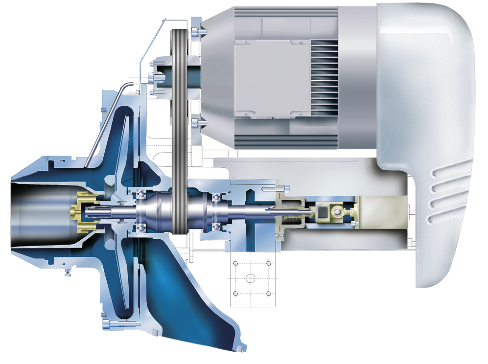
Sectional view of a rotary atomising burner (Saacke)
Oil supply
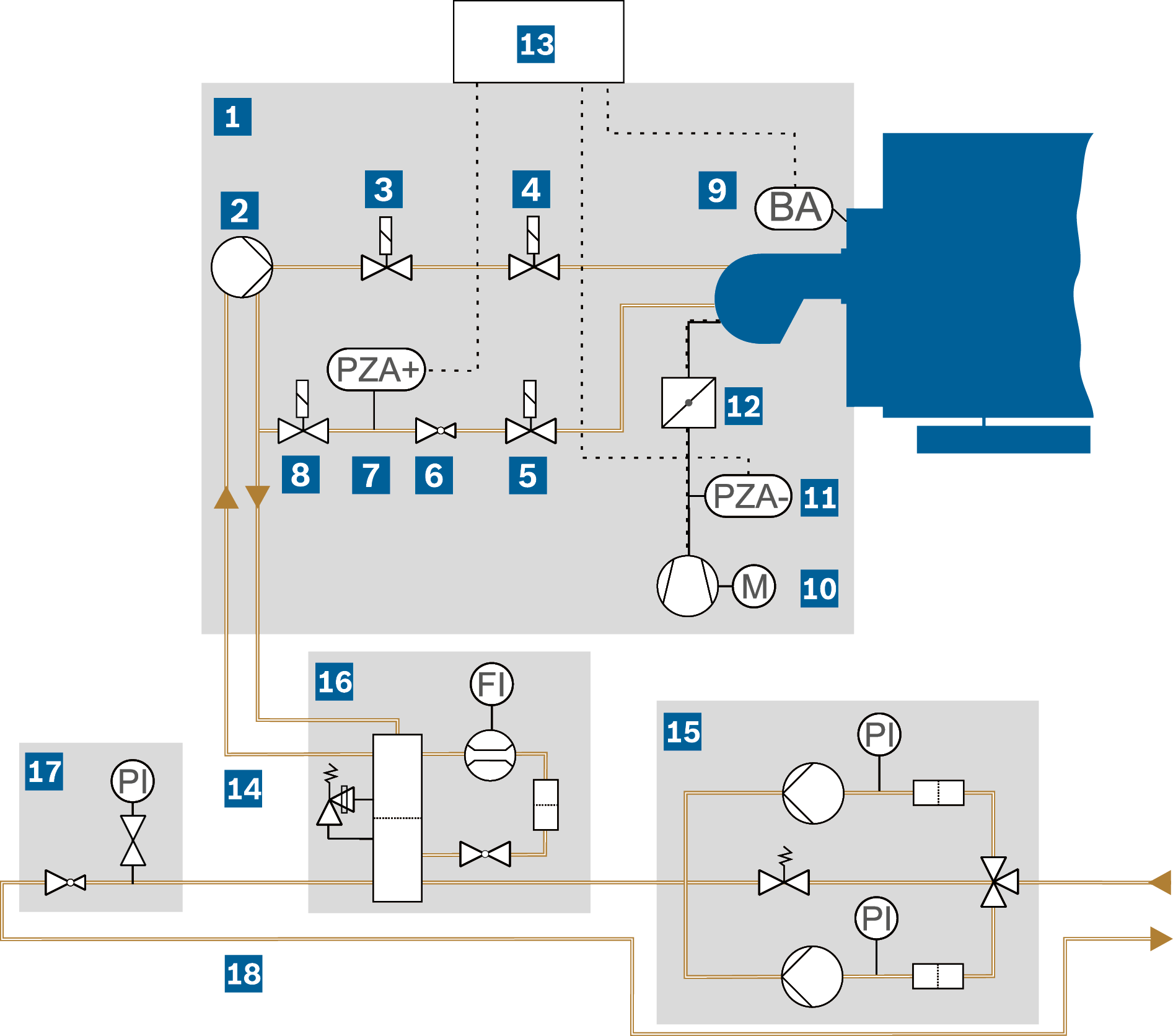
Example of a light fuel oil combustion system with pressure-jet oil burner
|
BA |
Flame monitoring |
|
FI |
Flow rate indicator |
|
PI |
Pressure indicator (pressure gauge) |
|
PZA- |
Air deficiency safety device |
|
PZA+ |
Maximum pressure limiter |
Combustion equipment
| Burner | Solenoid valve: second shut-off in oil return | |||
| Burner oil pump: generates the pressure of 12 – 30 bar required for atomisation |
Flame monitoring: switches the combustion system off if combustion in the combustion chamber is not stable after a starting time interval |
|||
| Solenoid valve: first shut-off of fuel supply in the oil flow | Fan: combustion air supply | |||
| Solenoid valve: second shut-off of fuel supply in the oil flow | Air deficiency safety device: shuts down the combustion system if the delivery pressure of the combustion air fan is low |
|||
| Solenoid valve: first shut-off in the oil return | Air damper: controls fuel/air ratio | |||
| Oil pressure controller: adjustment of oil pressure at the return flow atomiser of the burner depending on the required load |
Burner control unit/safety chain | |||
| Maximum pressure limiter: shuts down the combustion system if the oil pressure is too high |
Oil branch line | |||
| Oil supply | ||||
| Oil supply module OSM | Oil pressure regulation module ORM | |||
| Oil circulation module OCM | Oil ring line | |||
Oil supply module OSM
|
|
|
|
PI |
Pressure gauge |
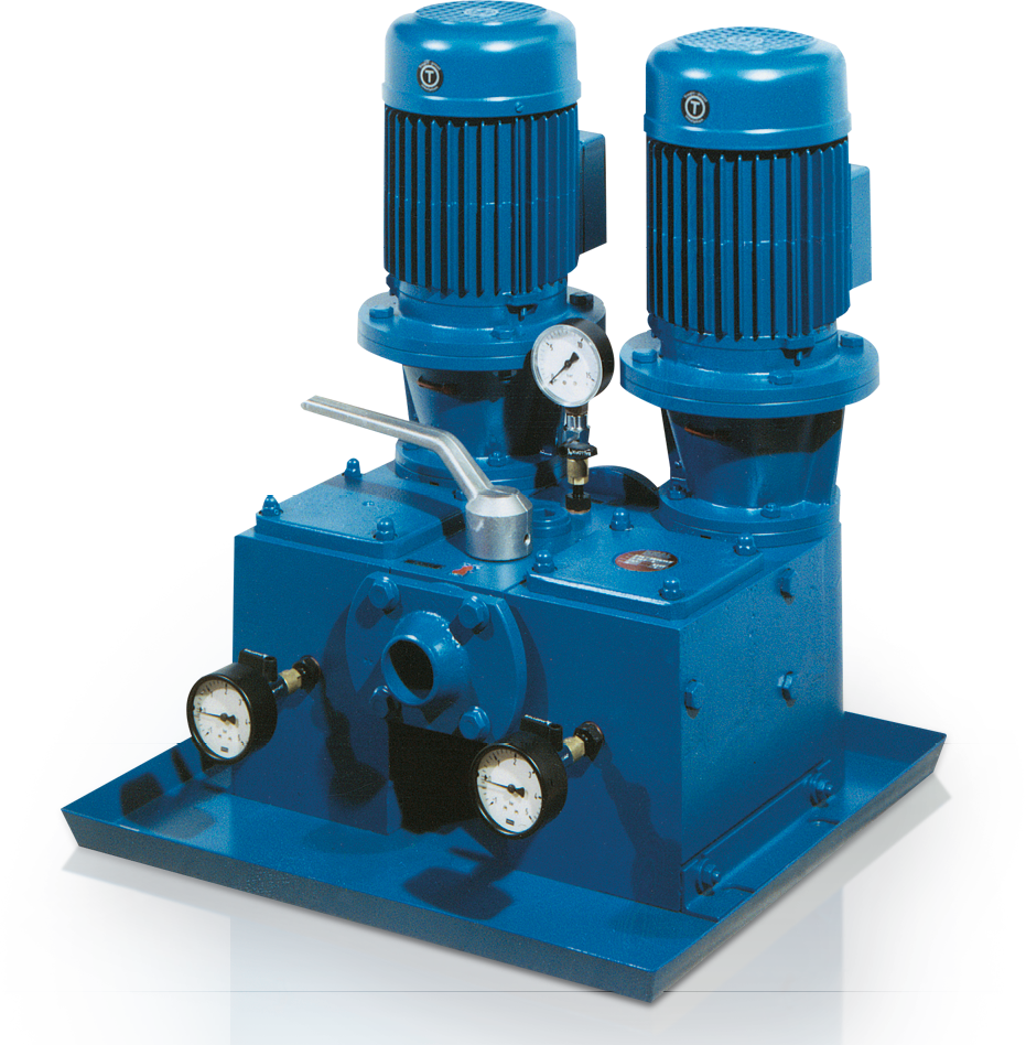
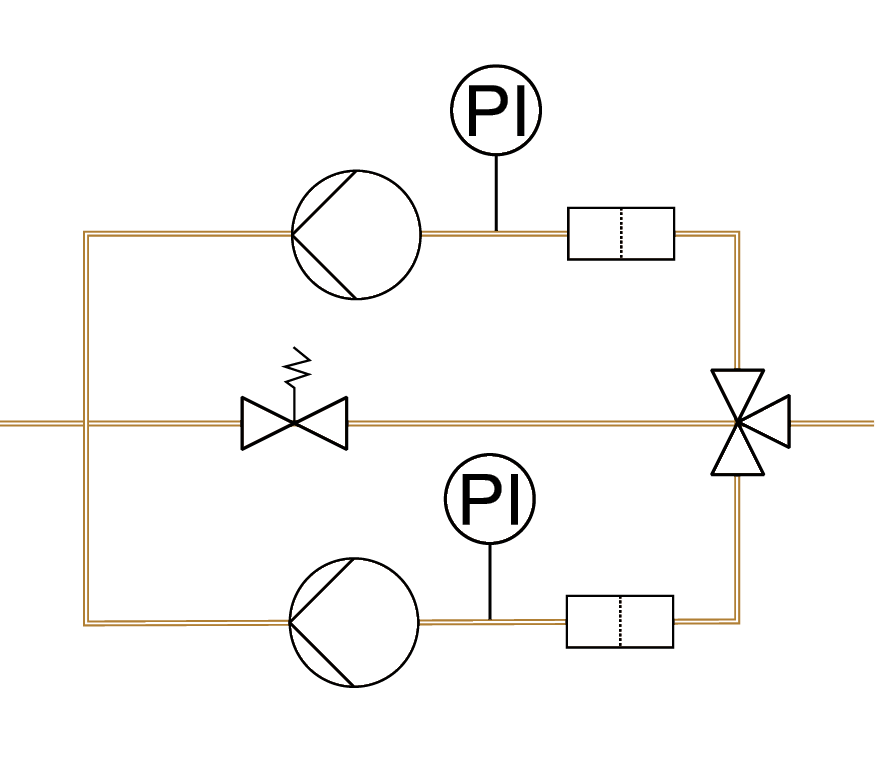
The oil supply module pumps the fuel from the oil storage tank which is set up outside the boiler house via the oil ring line to the individual oil circulation modules that supply each oil burner individually.
It is pre-assembled as a single or double station with 100% reserve to ensure security of supply, also in the event of an oil filter change, with all valves in an oil sump for ease of installation in the ring line.
Oil pressure regulation module ORM
|
|
|
PI |
Pressure gauge |
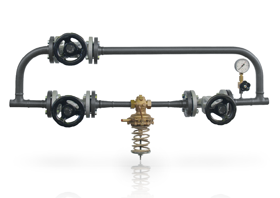
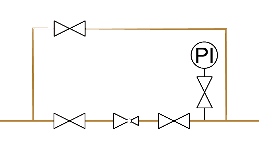
The purpose of the oil pressure regulation module is to set a constant oil pressure in the flow of the oil ring line. It consists of an oil pressure controller, upstream and downstream shut-off valves that allow the oil pressure controller to be removed, a pressure indicator (PI) and a bypass valve. It is always integrated downstream of the last branch line that supplies the burner.
Oil circulation module OCM
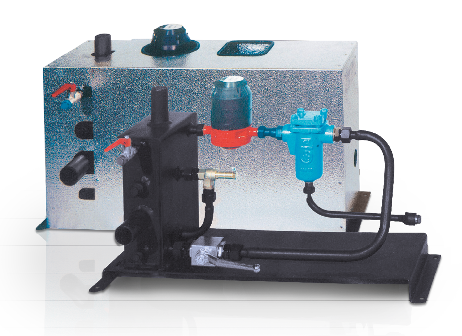
Oil circulation module |
|
|
FI |
Filter valve |
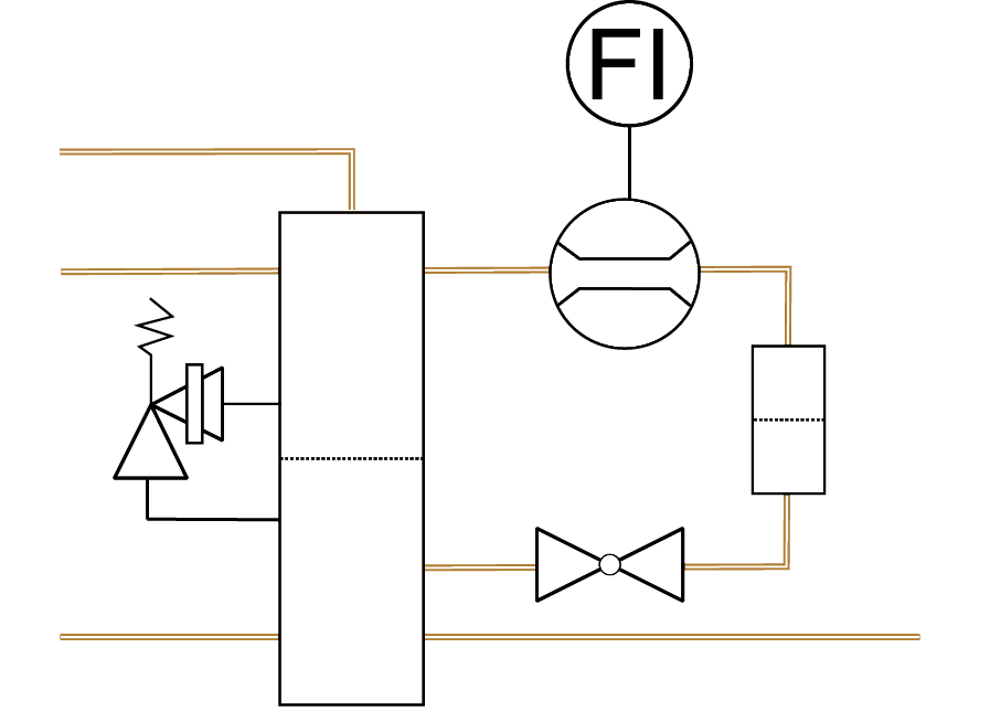
The oil circulation module prepares liquid fuels by means of filtering and air separation and measures the oil flow rate. It is designed for light and heavy fuel oil pressure-jet burners equipped with return flow atomiser system and is installed as ready-to-use unit including casing for every burner in the ring lines with a pre-charge pressure of ≥ 1.5 bar.
The module contains an oil reservoir with two chambers which supplies oil directly to the burner and receives the return flow quantity from the burner. The pipework can be directly connected to the oil hoses of the burner.
It includes a filter valve (FI), oil volumeter, shut-off valves, overpressure safety valve, ventilation shut-off valve and drain plug. In the case of heavy fuel oil operation, insulation is also fitted under the metal cladding.
Oil preheating module OPM
Oil preheating module |
|
|
TC |
Temperature control valve |
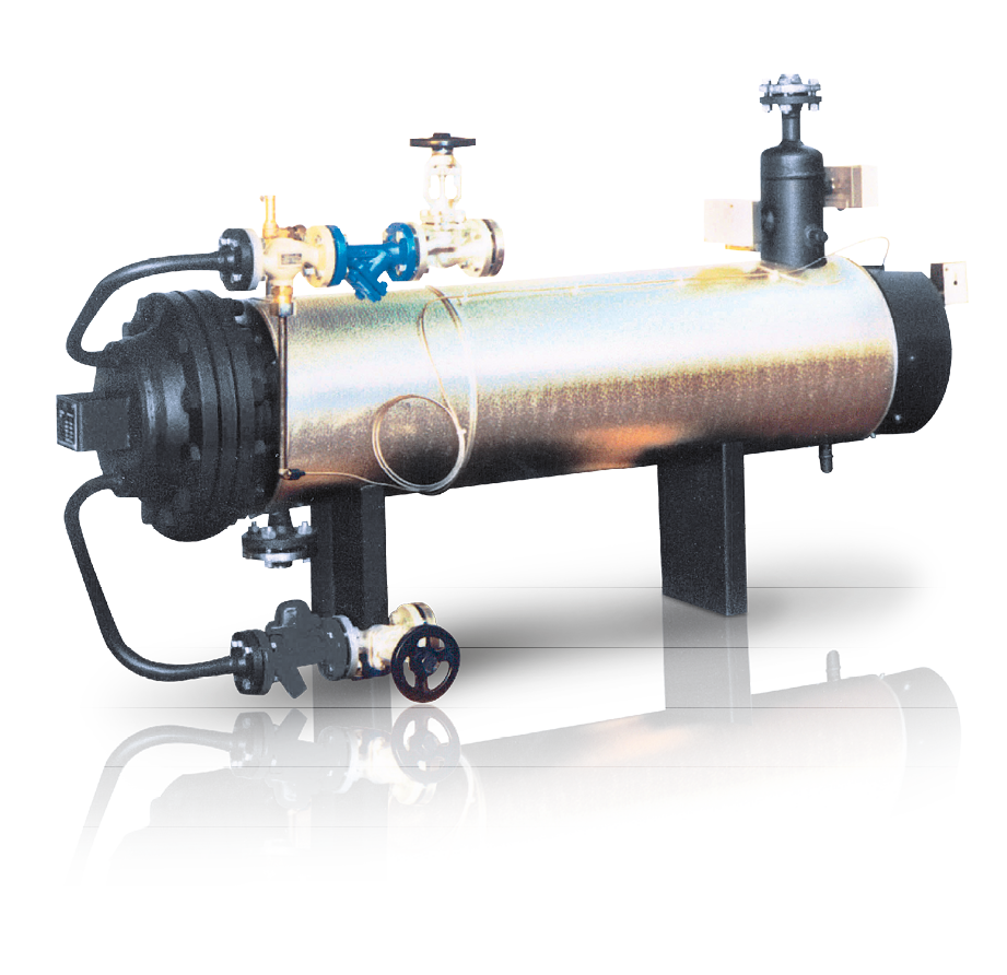
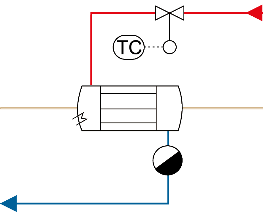
When using medium and heavy oils as fuel, they must be preheated because at ambient temperature they do not have the flow characteristics required for atomisation. The oil must be preheated in order to reduce the viscosity. Depending on the burner make and fuel, heating up to a temperature of 100 – 180°C is required to ensure reliable combustion.
The fuel is heated by a heat exchanger with extendable tube bundle which can be operated with steam or a combination of steam heating and electric heater. It must be ensured that trace heating is also fitted to all pipework and valves. In the start-up condition, the oil is initially heated by electricity then during continuous operation it is heated with steam to a constant temperature via the temperature control valve (TC). The module is pre-assembled ready to use, including the heating control, thermal insulation and all valves.
Combustion systems for gaseous fuels
Nowadays, natural gas is available at most locations and normally costs less than oil. The market share of gas combustion systems has been steadily increasing in recent years.
Info on Criteria for selection between fuel oil and natural gas
In addition to the economic advantage, using gas as fuel has other benefits:
- No fuel storage
- Less soiling of heating surfaces
- Less prone to faults
- Lower NOx and CO2 emissions
- More straightforward use of condensing technology
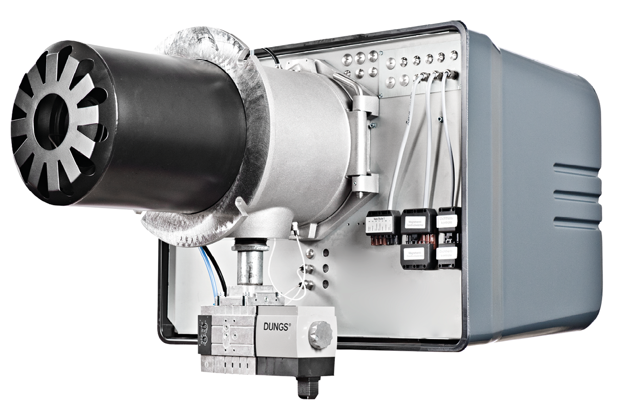
Burner with monoblock design (Dreizler) |
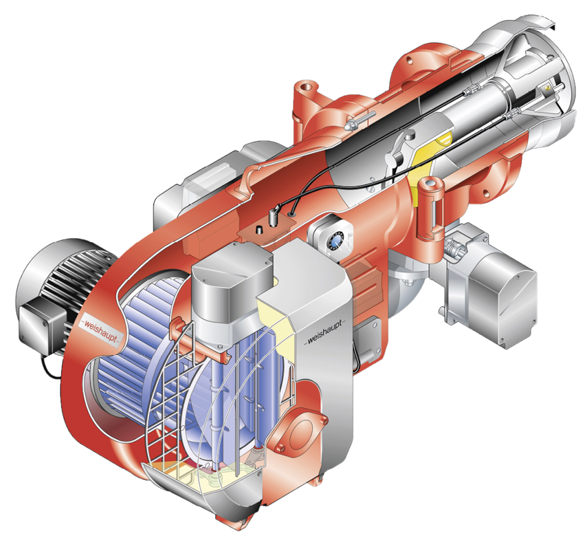
Sectional representation of gas burner (Weishaupt) |
Gas supply
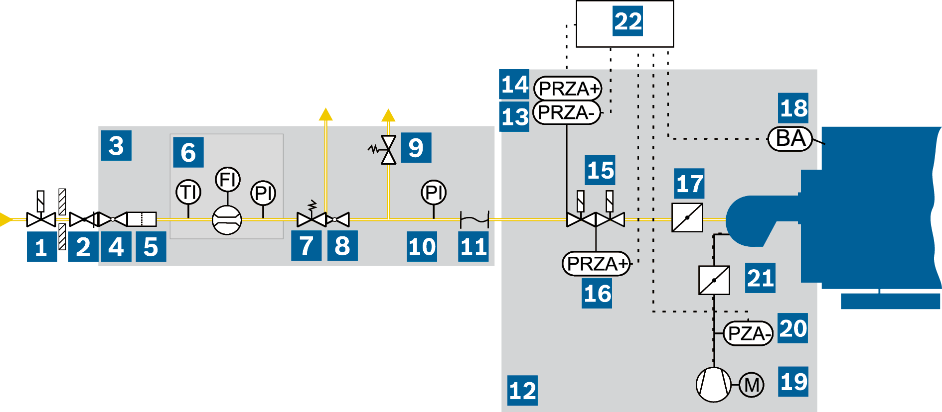
Example showing schematic representation of gas combustion (high-pressure supply)
|
Gas supply |
||||
|
BA |
Flame monitoring |
PRZA- |
Minimum gas pressure limiter |
|
|
FI |
Flow rate indicator |
PRZA+ |
Maximum gas pressure limiter |
|
|
PI |
Pressure indicator (pressure gauge) |
TI |
Temperature indicator |
|
|
PZA- |
Air deficiency safety device |
|
|
Safety shut-off valve: shuts off the gas supply |
|
Safety shut-off valve: locks out gas supply in the |
|
|
|
Thermal shut-off valve: shuts off the gas supply |
|
Gas pressure governor: ensures uniform gas |
|
|
|
Gas regulation module |
|
Safety relief valve: cuts in if an unacceptable |
|
|
|
Shut-off valve: for shutting off manually |
|
Pressure indicator (PI) |
|
|
|
Gas filter: protects sensitive parts from |
|
Expansion joint: compensates for pipework expansion |
|
|
|
Gas meter module: gas meter with temperature and pressure measurement for converting quantities from operation m³/h to standard m³/h |
|||
|
Combustion equipment |
||||
|
|
Burner |
|
Flame monitoring (BA): switches the combustion |
|
|
|
Minimum gas pressure limiter (PRZA-): |
|
Fan: combustion air supply |
|
|
|
Maximum gas pressure limiter (PRZA+): |
|
Air deficiency safety device (PZA-): shuts down the |
|
|
|
Double solenoid valve: double shut-off of gas |
|
Air damper: controls fuel/air ratio |
|
|
|
Tightness test (PRZA+): tests the tightness |
|
Burner control unit/safety chain |
|
|
|
Gas control damper: controls the gas volume |
|||
Gas regulation module GRM
|
|
|
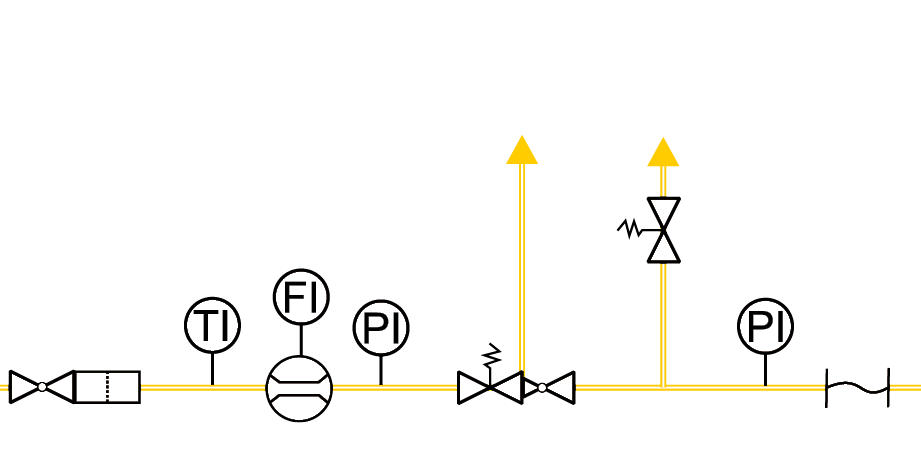
FI |
Flow rate indicator |
PI |
Pressure indicator (pressure gauge) |
TI |
Temperature indicator |
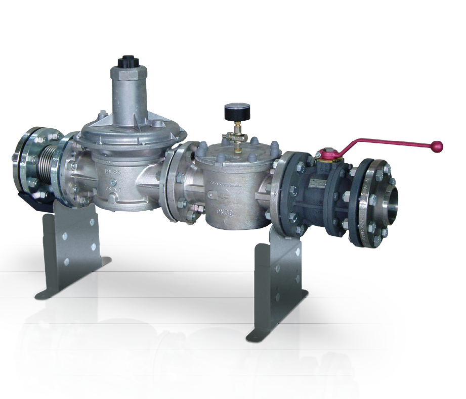
The gas regulation module contains all the control and safety equipment required for safe and fault-free combustion. The gas and air supply in particular are set via an electronic or pneumatic integrated control so that the correct fuel/air ratio for complete, safe and efficient combustion in the combustion chamber exists at all load points.
The gas pressure regulator is installed to ensure a uniform gas pressure upstream of the burner irrespective of the changing pre-charge pressures. If the gas pressure was changed, the gas/air ratio at the burner would change and consequently either an unstable flame or combustion leading to a heavy build-up of soot and CO formation would occur. If there is a possibility of the safeguarded upstream gas pressure exceeding the permissible operating pressure of the components of the gas train, then a safety shut-off valve and safety relief valve must be installed upstream of the control unit.
The pressure switches monitor the minimum and maximum permissible gas pressure if the gas pressure governor indicates a defect. During downtimes or pre-ventilation, gas must not enter the combustion chamber as otherwise a hard ignition may occur. The solenoid valves in the gas train must therefore close reliably. For safety reasons, the gas solenoid valves are redundantly configured and the burner sequence program checks before every burner start whether the valves are tight (gas tightness check).
Heating via waste heat gas
The heat of flue gases from upstream processes, e.g. combined heat and power from CHP modules or gas turbines, industrial manufacturing and production processes in the metal industry or the utilisation of thermal energy from waste material is suitable for generating steam in shell boilers.
Info on Combined heat and power
The possible steam output from the flue gases essentially depends on three criteria:
- Temperature level of the available flue gases
The higher the temperature level of the flue gas, the greater the achievable steam output. The temperature level can be up to around 300°C with micro gas turbines, 360 – 550°C with flue gases from engines or 1,000°C with industrial processes such as smelting or forging of tools or from utilisation of thermal energy. - Flue gas volume and duration of availability of flue gases
It must be considered whether flue gas will be available continuously or only at certain operating times. The quantity of flue gas must also be considered.
When using combined heat and power with a gas turbine, for example, up to 5 times more flue gas is available than that produced by an internal combustion engine with the same electrical output due to the large amount of excess air during combustion. - Pressure level at which the steam is to be made available
The higher the pressure level and therefore temperature of the saturated steam in the steam boiler, the lower the temperature gradient from the flue gas to steam which is available for heat transfer. For flue gas temperatures ≤ 330°C the operating pressure should ideally be < 5 bar. At higher flue gas temperatures, a higher steam pressure can be realised in the boiler.
Additional framework parameters for selection of a suitable boiler are the corresponding sulphur content, solids content or other corrosive substances, e.g. chlorine content in flue gas.
In this case, due to the large number of possible flue gas variations, detailed engineering is always recommended in preparation for a waste heat steam boiler system in order to use the available thermal energy as efficiently as possible.
